5
Installation
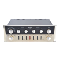
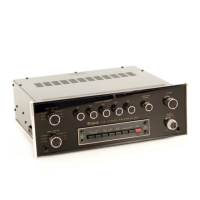
Front View of the C15
custom installed
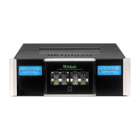
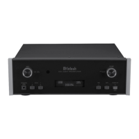
Side View of the C15
custom installed
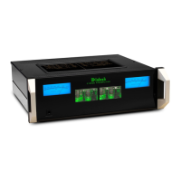
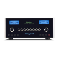
Bottom View of the C15 cus-
tom installed
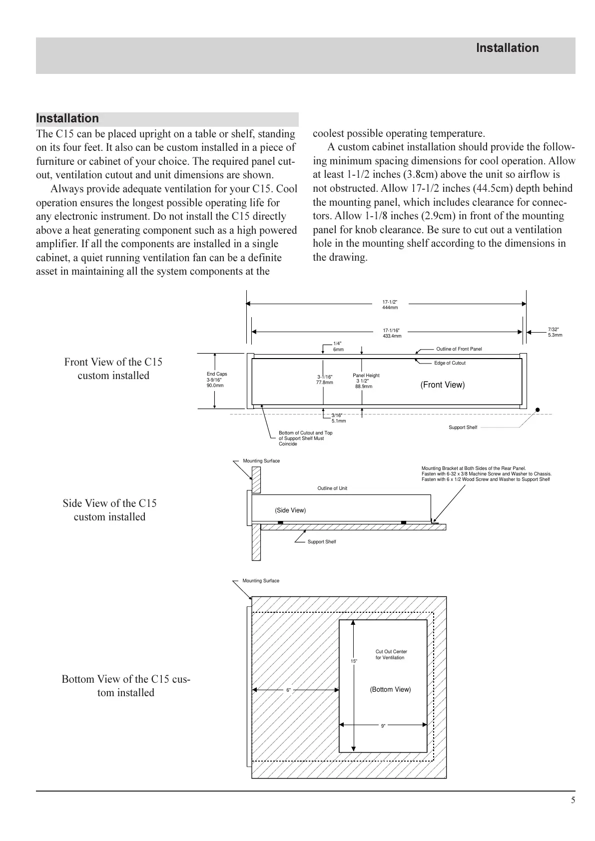
Installation
The C15 can be placed upright on a table or shelf, standing
on its four feet. It also can be custom installed in a piece of
furniture or cabinet of your choice. The required panel cut-
out, ventilation cutout and unit dimensions are shown.
Always provide adequate ventilation for your C15. Cool
operation ensures the longest possible operating life for
any electronic instrument. Do not install the C15 directly
above a heat generating component such as a high powered
amplifier. If all the components are installed in a single
cabinet, a quiet running ventilation fan can be a definite
asset in maintaining all the system components at the
coolest possible operating temperature.
A custom cabinet installation should provide the follow-
ing minimum spacing dimensions for cool operation. Allow
at least 1-1/2 inches (3.8cm) above the unit so airflow is
not obstructed. Allow 17-1/2 inches (44.5cm) depth behind
the mounting panel, which includes clearance for connec-
tors. Allow 1-1/8 inches (2.9cm) in front of the mounting
panel for knob clearance. Be sure to cut out a ventilation
hole in the mounting shelf according to the dimensions in
the drawing.
17-1/2"
444mm
17-1/16"
433.4mm
7/32"
5.3mm
Support Shelf
Outline of Front Panel
Edge of Cutout
Panel Height
3 1/2"
88.9mm
3-1/16"
77.8mm
1/4"
6mm
3/16"
5.1mm
End Caps
3-9/16"
90.0mm
Bottom of Cutout and Top
of Support Shelf Must
Coincide
Mounting Surface
Outline of Unit
(Side View)
Support Shelf
Mounting Bracket at Both Sides of the Rear Panel.
Fasten with 6-32 x 3/8 Machine Screw and Washer to Chassis.
Fasten with 6 x 1/2 Wood Screw and Washer to Support Shelf
6"
15"
9"
Mounting Surface
Cut Out Center
for Ventilation
(Bottom View)
(Front View)
 Loading...