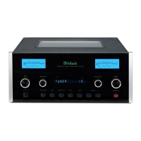
16
5. Press and hold in the INPUT Control until “SET-
UP: TRIGGER 1, (BAL 1: OFF)” Refer to figure
32.
Then rotate the INPUT Control to select which
one of the Inputs the TRIGGER 1 will switch OFF
when that input is selected. To change the Balance
1 Input status from “BAL 1: OFF” to BAL 1: ON
rotate the VOLUME (ADJUST) Control. Refer to
figure 33.
To make changes to the default Trigger 2 Setting,
perform steps 1 thru 5 again except select SETUP:
TRIGGER 2 first.
Power Control Triggers 1 and 2
By default the Power Control TRIGger 1 and TRIG-
ger 2 are assigned to activate when Output 1 or Output
2 is selected. Both Triggers can also be reassigned
to a given Input or Inputs or go On/Off with the C49
power.
In the first example, the Power Control Trigger 1
will be assigned to MAIN:
1. Press and hold in the INPUT Control to enter the
SETUP MODE. Refer to figure 2 on page 13.
2. Rotate the INPUT Control until “SETUP: TRIG-
GER 1, Main” appears on the Information Display.
Refer to figure 29.
3. Rotate the VOLUME (Adjust) Control until
“SETUP: TRIGGER 1, Output 1” appears on the
Information Display. Refer to figure 30.
4. Rotate the VOLUME (ADJUST) Control again to
select “SETUP: TRIGGER 1, Input (Hold IN-
PUT)”. Refer to figure 31.
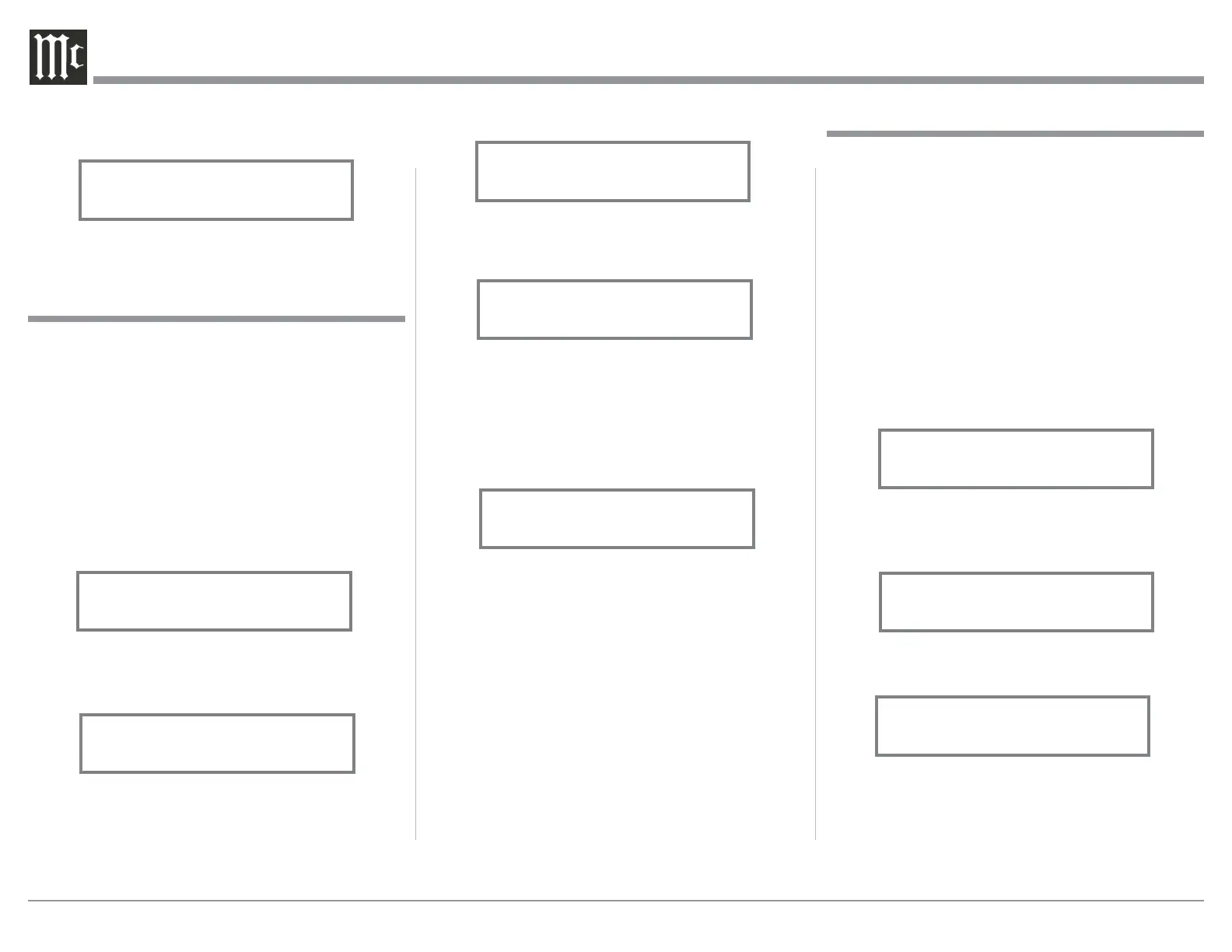
Figure 29
SETUP: TRIGGER 1
Main
Figure 30
SETUP: TRIGGER 1
Output 1
Figure 33
SETUP: TRIGGER 1
BAL 1: ON
Data Ports
Data Ports Connections between the C49 and a Mc-
Intosh Source Component allow for basic function
control of the source component using the C49 sup-
plied HR085 Remote Control. By default, all of the
four Data Ports are set to send the same Data to the
selected source. To dedicate a given Data Port for only
one source component (example, source component
connected to the BAL 1 Input will be assigned to Data
Port 1) perform the following Steps:
1. Press and hold in the INPUT Control to enter the
SETUP MODE. Refer to figure 2 on page 13.
2. Rotate the INPUT Control until “SETUP: Data
Ports, (Hold INPUT)” appears on the Information
Display. Refer to figure 34.
3. Press and hold in the INPUT Control until “SET-
UP: DATA PORT 1, All Data” appears on the
Display. Refer to figure 35.
4. Rotate the VOLUME (ADJUST) Control to select
“BAL 1” Input. Refer to figure 36.
5. In a similar manner, perform steps 3 and 4 to as-
sign any additional Data Ports.
6. Exit the SETUP Mode by several presses of the
INPUT Control.
Figure 34
(Hold INPUT)
Figure 35
SETUP: DATA PORT 1
All Data
Figure 36
SETUP: DATA PORT 1
BAL 1
f igu res 27.
8. Exit the SETUP Mode by several presses of the
INPUT Control.
Figure 27
SETUP: HEADPHONES
Figure 31
SETUP: TRIGGER 1
Input (Hold INPUT)
Figure 32
SETUP: TRIGGER 1
BAL 1: OFF
 Loading...