OM 750 Page 19 of 32
OCCUPIED MODE
The occupied mode is the normal day time mode of UVC operation.
During occupied mode the UVC will use the occupied heating and
cooling setpoints, the OAD will operate normally, and by default the
IAF will remain on.
UNOCCUPIED MODE
The unoccupied occupancy mode is the normal night time mode of
UVC operation. During unoccupied mode the UVC will use the
unoccupied heating and cooling setpoints, the OAD will remain closed,
and the IAF will cycle as needed for heating or cooling. The IAF will
remain off when there is no need for heating or cooling.
STANDBY MODE
The standby mode is a special purpose day time mode of UVC
operation. During standby mode the UVC will use the standby heating
and cooling setpoints, the OAD will remain closed, and by default the
IAF will remain on.
BYPASS MODE
The bypass mode (also called Tenant Override) is the equivalent of a
temporary occupied mode. Once the bypass mode is initiated it will
remain in effect for a set period of time (120-minutes default). During
the bypass mode the UVC will use the occupied heating and cooling
setpoints, the OAD will operate normally, and by default the IAF will
remain on.
NETWORKED OCCUPANCY SENSOR CAPABILITY
A networked occupancy sensor can be interfaced with the Occupancy
Sensor Input variable to select occupancy modes. When the Occupancy
Sensor Input variable is used, it will automatically override any hard-
wired unoccupied binary input signal.
UNIT-MOUNTED TIME-CLOCK
An optional unit-mounted factory-installed electronic 24-hour/7-day
time clock can be provided on some unit ventilator configurations. This
time clock is factory wired to the UVC unoccupied binary input and can
be set to automatically place the unit into occupied and unoccupied
modes based upon its user configured schedule.
UNIT-MOUNTED TENANT OVERRIDE SWITCH
A tenant override switch is factory installed in all floor mounted units.
This tenant override switch is located near the LUI on the unit. The
tenant override switch provides a momentary contact closure that can
be used by room occupants to temporarily force the UVC into the
bypass occupancy mode from unoccupied mode.
REMOTE WALL-MOUNTED SENSOR TENANT
OVERRIDE SWITCH
The optional remote wall-mounted sensors include a tenant override
switch. This tenant override switch provides a momentary contact
closure that can be used by room occupants to temporarily force the
UVC into the bypass occupancy mode from unoccupied mode.
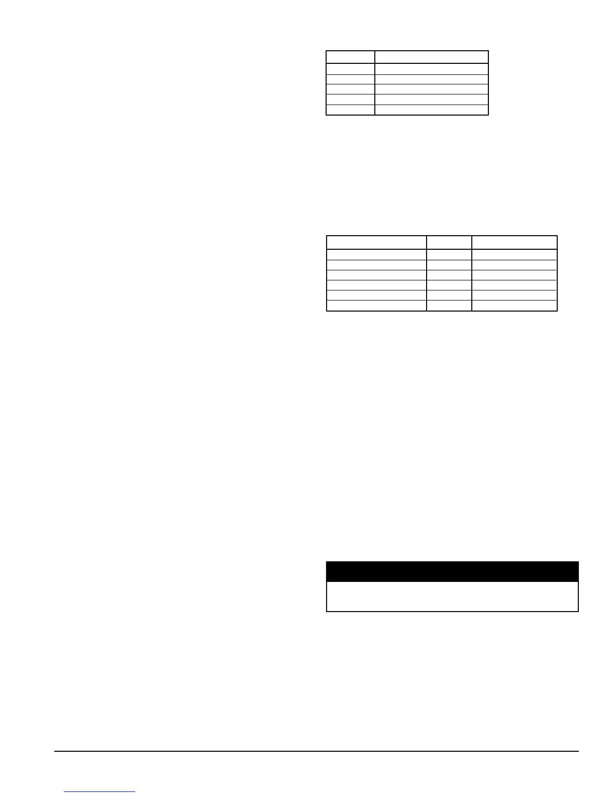
REMOTE WALL-MOUNTED SENSOR STATUS LED
The optional remote wall-mounted sensors each include a UVC status
LED. This status LED aids is diagnostics by indicating the UVC
occupancy mode and fault condition.
Indication LED Operation
Occupied On Continually
Unoccupied On 1-sec / Off 9-sec
Bypass On Continually
Standby On 9-sec / Off 1-sec
Fault On 5-sec / Off 5-sec
Table 12. Remote Wall-Mount Sensor Status LED
Space Temperature Setpoints
The UVC uses the six occupancy-based temperature setpoints as the
basis to determine the Effective Setpoint Output. The UVC will
calculate the effective setpoint based upon the unit mode, the occupancy
mode, and the values of several network variables. The effective
setpoint is then used as the temperature setpoint that the UVC will
maintain.
Temperature Setpoints Abr. Defaults
Unoccupied Cool UCS 82.4
O
F (28.0
O
C)
Standby Cool SCS 77.0
O
F (25.0
O
C)
Occupied Cool OCS 73.4
O
F (23.0
O
C)
Occupied Heat OHS 69.8
O
F (21.0
O
C)
Standby Heat SHS 66.2
O
F (19.0
O
C)
Unoccupied Heat UHS 60.8
O
F (16.0
O
C)
Table 13. Default Occupancy-based Temp Setpoints
NETWORKED SETPOINT CAPABILITY
The Space Temp Setpoint Input variable is used to allow the temperature
setpoints for the occupied and standby modes to be changed via the
network, the unoccupied setpoints are not effected by this variable.
NETWORKED SETPOINT OFFSET CAPABILITY
The Setpoint Offset Input variable is used to shift the effective
occupied and standby temperature setpoints by adding the value of the
Setpoint Offset Input variable to the current setpoints, the unoccupied
setpoints are not effected by this variable. This variable is typically
bound to a supervisory network controller (by others) or to a networked
wall module (by others) having a relative setpoint adjustment.
NETWORKED SETPOINT SHIFT CAPABILITY
The Setpoint Shift Input variable is used to shift the effective heat/cool
setpoints. It is typically bound to a networked supervisory controller
which provides functions such as outdoor air temperature compensation.
All occupied, standby and unoccupied setpoints will be shifted upward
(+) or downward (-) by the corresponding value of the Setpoint Shift
Input variable.
The Setpoint Shift Input capability is not available through the
BACnet® interface.
NETWORKED SPACE TEMPERATURE
SENSOR CAPABILITY
A networked space temperature sensor can be interfaced with the
Space Temp Input variable. When the Space Temp Input variable is
used (valid value), it will automatically override the hard-wired space
temperature sensor.
NOTICE

 Loading...


