OM 750 Page 27 of 32
All UVC input and output connections and their corresponding unit
ventilator usage are shown in the following table.
Table 20. Inputs and Outputs for Software Model 04 – DX Cooling
with Electric Heat
Description
BO-1 Inside Fan High
BO-2 Inside Fan Medium
BO-3 Electric Heat 1
BO-4 Electric Heat 2
BO-5 Electric Heat 3
BO-6 External Output Option 3: Fault Indication
햳
BO-7
BO-8
BO-9 Compressor
햶
BI-1 Condensate Overflow
BI-2
BI-3
BI-4 External Input Option 1: Ventilation Lockout (default)
or Exhaust Interlock
햴
BI-5 External Input Option 2: Remote Shutdown 햴
BI-6 External Input Option 3: Unoccupied (default) or
Dewpoint/Humidity
햴
BI-7
BI-8
BI-9
BI-10
BI-11
BI-12 DX Press Switch (NC)
햵
AI-1 IA Temp. Sensor + T.O.
UVC INPUT AND OUTPUT TABLE
The most important aspect of troubleshooting unit ventilator controls
is to isolate the source of the problem into one of two categories: 1) the
problem resides within the UVC, or 2) the problem is external to the
UVC. Under most circumstances the problem will reside external to the
UVC.
Alarm and Fault Monitoring
The UVC is programmed to monitor the unit for specific alarm
conditions. If an alarm condition exists, a fault will occur. When a fault
condition occurs, the UVC will indicate the fault condition by displaying
the fault code on the LUI, the remote wall-mounted sensor (optional)
LED will flash a pattern indicating that a fault condition exists, the fault
signal binary output will be energized, and the UVC will perform the
appropriate control actions.
Manual reset faults can be reset in one of three ways: 1) cycle unit
power, 2) LUI menu, or 3) via network interface.
AI-2 Remote Setpt. Adjust. Pot.
AI-3 DA Temp Sensor
AI-4 OA Temp Sensor
AI-5 IA Coil DX Temp Sensor
AI-6 OA Coil DX Temp Sensor
햷
Expansion Board
xBO-1 External Output Option 2: Lights On/Off
햳
xBO-2 External Output Option 1: Exhaust Fan On/Off
햳
xBO-3 OA Damper Open
xBO-4 OA Damper Close
xBO-5
xBO-6
xBO-7 Outdoor Fan
햷
xBO-8 Inside Fan Low
xAI-1 IA Humidity Sensor
햲
xAI-2 OA Humidity Sensor
햲
xAI-3 Indoor CO
2
Sensor
햲
xAI-4
햲 Optional.
햳 Field selectable external output options (all possible options are shown.)
햴 Field selectable external input options (all possible options are shown.)
햵 DX pressure switch not installed on split-systems, this input will then be
wired for constant no-fault condition.
햶 This is the condensing unit on/off signal on split-systems.
햷 Not installed or wired on split-systems.
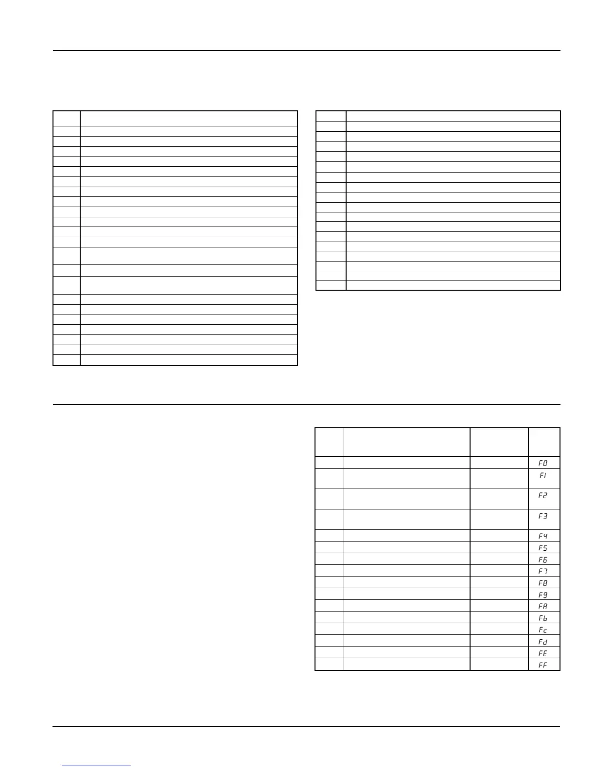
DIAGNOSTICS AND SERVICE
LUI
Priority Fault Description Reset Fault
Codes
1 Space Temp Sensor Failure Auto
2 DX Pressure Fault 2-Auto in 7-days
then Manual
3 Compressor Envelope Fault 2-Auto in 7-days
then Manual
4 Discharge Air DX Auto
Cooling Low Limit Indication
5 Condensate Overflow Indication Auto
6 Space Coil DX Temp Sensor Failure Auto
7 Outdoor Temp Sensor Failure Auto
8 Discharge Air Temp Sensor Failure Auto
9 Outdoor Coil DX Temp Sensor Failure Auto
10 Not Used
11 Space Humidity Sensor Failure Auto
12 Outdoor Humidity Sensor Failure Auto
13 Space CO
2
Sensor Failure Auto
14 Not Used
15 Not Used
16 Change Filter Indication Manual
Table 21. Alarm and Fault Code Summary

 Loading...


