4 McQuay IM 987
Introduction
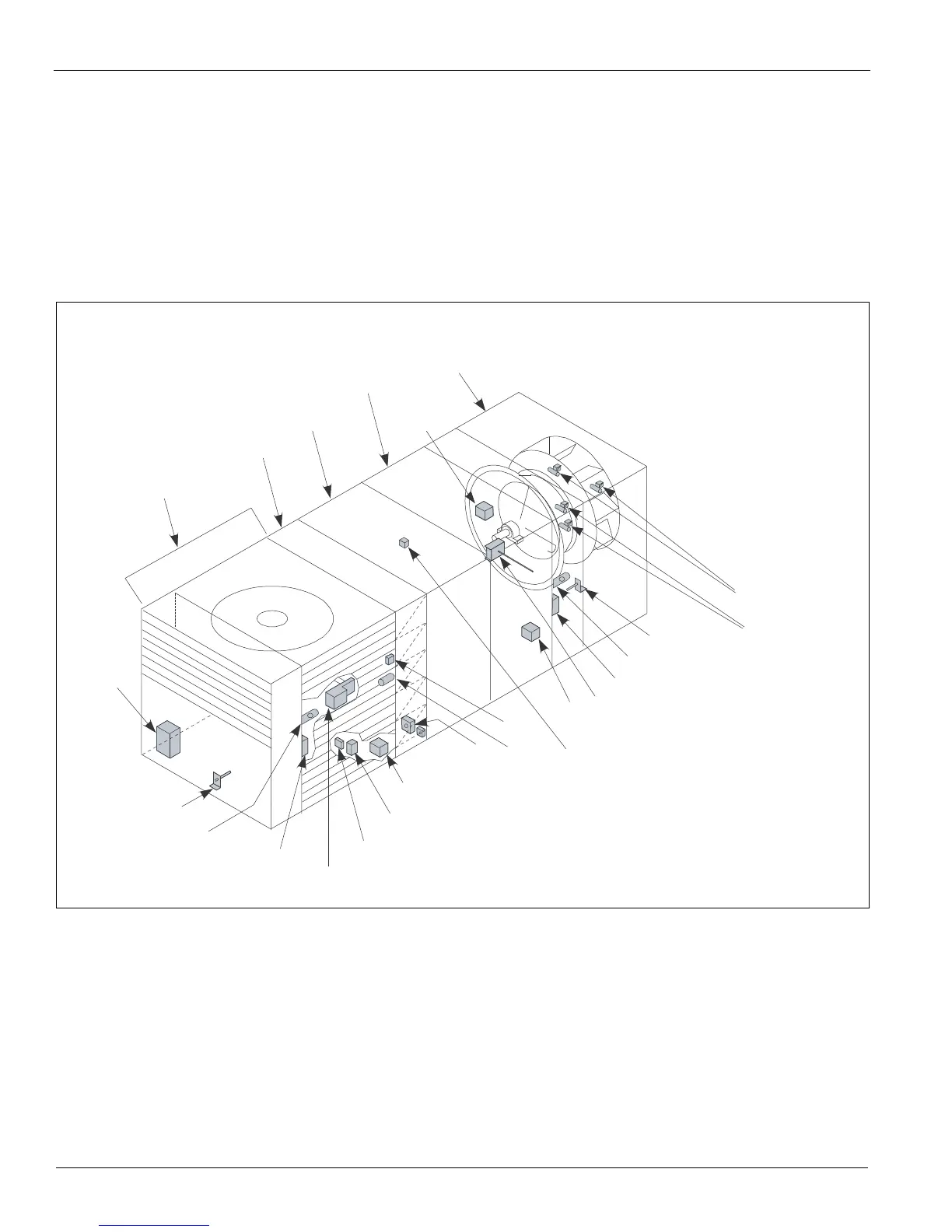
Typical Component Locations
Figure 2 shows a typical unit with locations of major
components. These figures are for general information only.
See the project’s certified submittals for actual specific
dimensions and locations.
Control Locations
All controls are optional. If controls are ordered, Figure 2
shows the locations of the various control components
mounted throughout the units. See Figure 3, page 5 for the
locations of control components mounted in control panels.
Additional information is included in Table 2, page 12 and the
wiring diagram legend, which is included in "Wiring
Diagrams"‚ page 59. Figure 2 shows the blow-through heat
and the blow-through coil sections.
Figure 2: Control Locations
Economizer
Filter
DX
Heat
section
Supply fan
discharge
plenum
section
C19, 20
RAT
LT11 (optional)
S11, REC11
SD2
RAE
ACT3
PC5
OAE
VM1
LT10 (optional)
DAT
OAT
SV1, 2
(optional)
section
section
return air
(optional)
(optional)
(optional)
(optional)
C9
FS1
(optional)
SV5, 6 (optional)
S10, REC10 (optional)
SD1 (optional)
ACT6
 Loading...


