84 McQuay IM 987
Unit Options
Unit Options
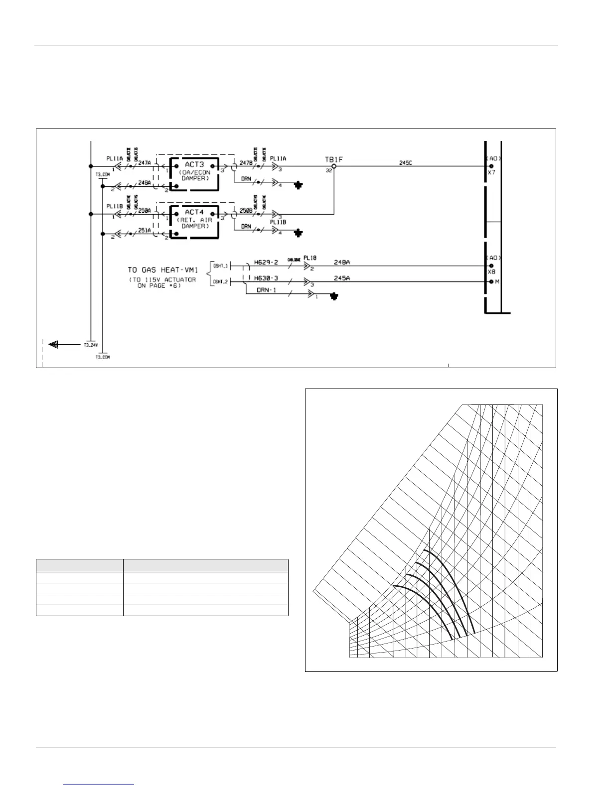
Control Actuators
The actuators are controlled by an analog signal from the unit
controller. Damper actuators utilize a 0-10 V (dc) analog
signal while modulating heating/cooling valve actuators utilize
a 2-10 V (dc) signal. Spring-return actuators are used for the 0
- 30% outdoor air and economizer dampers. The mixing
dampers are normally closed to the outside air.
Figure 93: Control Actuators Wiring Diagram
Enthalpy Control
Outside Air Enthalpy Control (OAE)
Units with MicroTech III control and an economizer come
standard with an electromechanical enthalpy control device
(OAE) that senses both the humidity and temperature of the
outside air entering the unit. This device has an enthalpy scale
marked A through D. Table 14 shows the control points at 50%
RH for settings A through D. Figure 94 shows this scale on a
psychrometric chart. When the outside air conditions exceed
the setting of the device, the outside air dampers are positioned
to the minimum outside air intake position by the MicroTech
III controller.
Figure 94: Enthalpy Control Settings
REC1
FIELD SUPPLIED 115V/60/1
Table 14: Enthalpy Control Settings
Control curve Control point temperature at 50% RH
A73°F (23°C)
B70°F (21°C)
C 67°F (19*C)
D63°F (17°C)
3 5
( 1 . 5 )
4 0
( 4 . 5 )
4 5
( 7 )
5 0
( 1 0 )
6 0
( 1 5 . 5 )
6 5
( 1 8 . 5 )
7 0
( 2 1 )
7 5
( 2 4 )
8 0
( 2 6 . 5 )
8 5
( 2 9 . 5 )
9 0
( 3 2 )
9 5
( 3 5 )
1 0 0
( 3 8 )
1 0 5
( 4 0 . 5 )
5 5
( 1 3 )
1 2
1 4
1 6
1 8
2 0
2 2
2 4
2 6
3 0
3 2
3 4
3 6
3 8
4 0
4 2
4 4
4 6
2 8
E N T H A L P Y B T U P E R P O U N D D R Y A I R
C
B
A
D
D
C
B
A
0 . 5 0
0 . 4 0
0 . 3 0
0 . 2 0
0 . 1 0
0 . 6 0
0 . 7 0
0 . 8 0
0 . 9 0
R E L A T I V E
H U M I D I T Y
3 5
( 1 . 5 )
4 0
( 4 . 5 )
4 5
( 7 )
5 0
( 1 0 )
5 5
( 1 3 )
6 0
( 1 5 . 5 )
6 5
( 1 8 . 5 )
7 0
( 2 1 )
7 5
( 2 4 )
8 0
( 2 6 . 5 )
8 5
( 2 9 . 5 )
9 0
( 3 2 )
9 5
( 3 5 )
1 0 0
( 3 8 )
1 0 5
( 4
0 . 5 )
 Loading...


