22 McQuay IM 987
Mechanical Installation
Post and Rail Arrangement
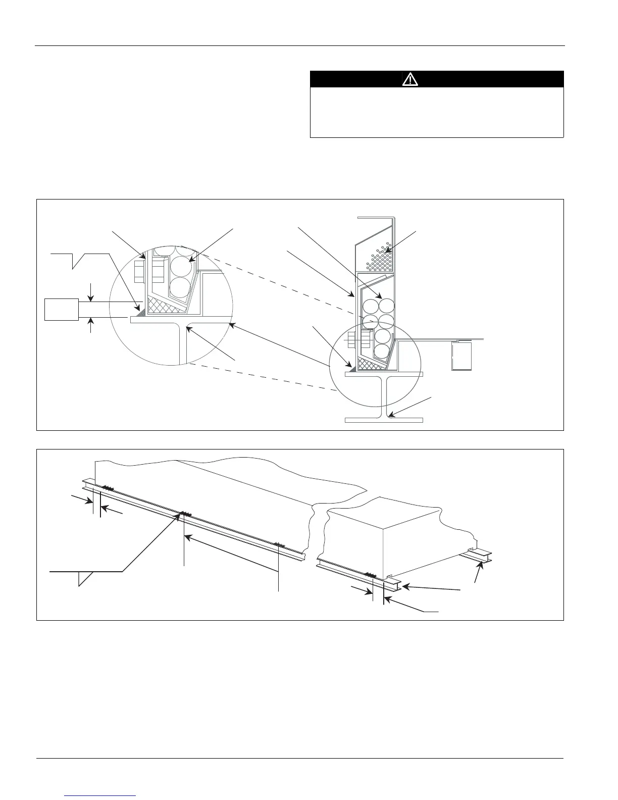
1 Set the rooftop unit on the rails. The rails should run
lengthwise and support the entire unit base.
2 Weld both sides of the unit directly to each rail as shown
in Figure 24 and Figure 25.
The total number of welds
required is dependent on the length of the unit.
a Make the fillet welds 2 inches long, spaced 48 inches
apart on centers.
b Place the end welds 6 to 12 inches from the unit edge.
Note: High temperature insulation is installed at the factory to
allow for field welding along the lower front edge region
of the unit base.
Figure 24: Welding of Unit To Rail—Unit Base, Cross-Sectional View
Figure 25: Weld Locations for Rail Arrangement
CAUTION
When welding unit to the curb, do not damage wiring (control
panel side). Weld ONLY in the specified zone in the acceptable
weld zone (see Figure 24). Welding must comply with weld
fillet size, etc. as indicated in Figure 24.
2–48
Rail
.25
Unit power wiring
(by factory)
Unit control wiring
(by factory)
High temp
insulation
Rail
Acceptable weld zone
Field attachment
weld
Weld
zone
.50"
Unit base
Unit base
6–12"
2–48
Rooftop unit
.25
Weld every 48"
6–12"
Rails
 Loading...


