90 McQuay IM 987
Unit Options
14 Set up the leveling test as follows:
a While holding the weight so it stays on the fulcrum,
manually rotate the vane to the wide-open position,
manually return it to the zero CFM position, and
gently release the vane.
b Locate the leveling weight assembly so its contact
point is against the vertical mark on the vane.
c While the weight assembly teeters on the fulcrum,
gently rap the base frame to slightly vibrate the
assembly and encourage the vane to seek its
equilibrium point.
15 Read the current LH Lvl Pos= (or RH Lvl Pos=)
parameter in the DesignFlow Setup menu on the keypad/
display. These parameters vary from 20% to 80%
depending on the position of the DesignFlow vane
16 If the value indicated by the LH Lvl Pos= (or RH Lvl
Pos=) parameter is not within the range of 22.56% to
23.02%, (22.79% is ideal) adjust the level of the
DesignFlow unit using the procedure described in
“Making Level Adjustments” below.
17 When the LH Lvl Pos= (or RH Lvl Pos=) value is in
range, remove the fulcrum and leveling weight assembly
and replace the access opening cover in the louvered
door.
Making Level Adjustments
The DesignFlow unit is mounted so that it pivots at the top
when three lock nuts are loosened, two at the top and one at
the bottom of the assembly (see Figure 101). Leveling the unit
involves precisely pivoting the assembly with a known force
applied to the vane until the vane opens to a specific position.
If after performing Steps 13 through 15 (previous page), the
vane does not come to rest within the specified range, carry out
the following steps:
1 Unlock and open the louvered outdoor air intake door on
the side of the unit.
2 Loosen the two 1/4-20 NC lock nuts at the top of the
DesignFlow frame (see Figure 101).
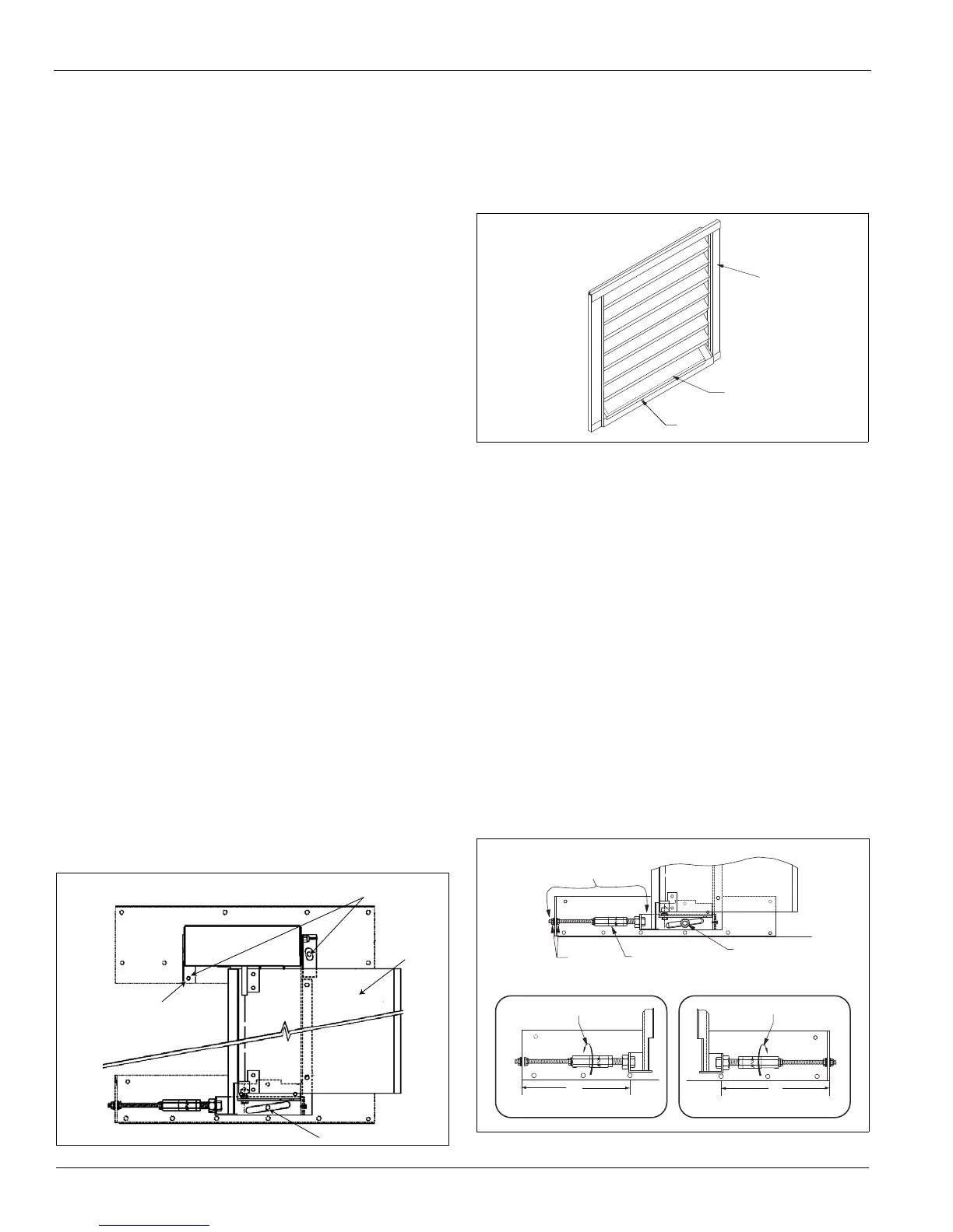
Figure 101: DesignFlow Frame
3 Close and lock the intake door.
4 Remove the cover from the access opening in the bottom
blade of the outdoor air intake louver (see Figure 102).
5 Loosen the 1/4-20 NC lock nut in the slotted hole at the
bottom of the DesignFlow frame (see Figure 103).
Figure 102: Remove Covers from Access Opening
6 If the LH Lvl Pos= (or RH Lvl Pos=) value obtained in
step 15 above is HIGHER than the specified range,
move the bottom of the DesignFlow frame closer to the
outdoor air dampers (away from the back end of the
unit). Do this by turning the long adjuster nut to increase
the L dimension in Figure 103.
If the LH Lvl Pos= (or RH Lvl Pos=) value obtained in
step 15 above is LOWER than the specified range,
move the bottom of the DesignFlow frame away from
the outdoor air dampers (toward the back end of the
unit). Do this by turning the long adjuster nut to decrease
the L dimension in Figure 103.
Note: If the necessary adjustment cannot be made using
the long adjuster nut, reposition the two 1/4-20 NC
jam nuts on the threaded rod to make larger
adjustments (see
Figure 103).
7
When finished making the adjustments, tighten the
1/4-20 NC lock nut in the slotted hole at the bottom of
the DesignFlow frame (see Figure 103).
Figure 103: Leveling Adjustment
Top lock nuts
Vane
Bottom lock nut
Pivot point
Louvered
door
Access opening
Cover
Threaded adjuster
assembly
Long adjuster nut
Jam nuts
Locknut
To INCREASE L dimension
L
To INCREASE L dimensi
L
Right hand adjuster Left hand adjuster
 Loading...


