UNIT WITH FACTORY MOUNTED CONDENSER(S)
Units with factory mounted condensers are provided with
complete refrigerant piping and full operating refrigerant
charge at the factory.
There is a remote possibility on Arrangement W units utiliz-
ing low temperature pond or river water as a condensing
medium, and if the water valves leak, that the condenser and
liquid line refrigerant temperature could get below the equip-
ment room temperature on the off cycle. This could open the
expansion valve and cause recycling pumpdown. This
prob-
lem
only arises during periods when cold water continues to
circulate through the condenser and the unit remains off due
to satisfied cooling load.
If this condition occurs:
1.
2.
Cycle the condenser pump off with the unit.
Check the liquid line solenoid valve for proper operation.
If these valves are closing liquid tight as designed, no
recycling of
pumpdown
should occur.
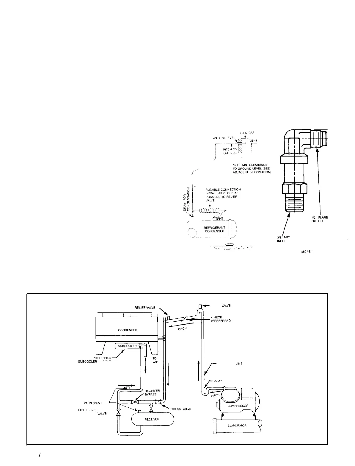
RELIEF VALVE PIPING
The ANSMASHRAE Standard 15-1978 specifies that pressure
relief valves on vessels containing Group 1 refrigerants (R-12,
R-22 and R-500) “shall discharge to the atmosphere at a loca-
tion not less than 15 feet above the adjoining ground level
and not less than 20 feet from any window, ventilation open-
ing or exit in any building.” The piping must be provided with
a rain cap at the outside terminating point and a drain at the
low point on the vent piping to prevent water buildup on the
atmospheric side of the relief valve. In addition, a flexible pipe
section should be installed in the line to eliminate any piping
stress on the relief valve(s).
The size of the discharge pipe from the pressure relief valve
shall not be less than the size of the pressure relief outlet.
When two or more vessels are piped together, the common
header and piping to the atmosphere shall not be less than
the sum of the area of the relief valve outlets connected to
the header. Fittings should be provided to permit vent pip-
ing to be easily disconnected for inspection or replacement
of the relief valve.
NOTE: Provide adequate fittings in piping to permit repair
or replacement of relief valve.
Figure
13. Relief Valve Piping
REFRIGERANT PIPING
Figure 14. Condenser Above Compressor and Receiver
RELIEF VALVE
(SET AT
4%
PSI1
REM3
VALVE
PURGE
VALVE
GHECK VALVE’
iPREFERRED,
SUBCOOLER HOOKUP
DISCHARGE LINE
RELIEF
VALVE
(VENT TO
OUTDOORS OR TO CONDENSER
SIDE OF IIOUID LINE CHECK
VALVE)
Page 14
I
IM 508
 Loading...