www.DaikinApplied.com 11 IOM 1210-1 • MAGNITUDE
®
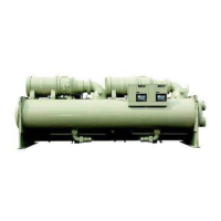
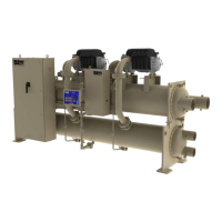
MODEL WMC CHILLERS
Field Insulation
If the optional factory-installation of thermal insulation is not
ordered, insulation should be eld installed to reduce heat
loss and prevent condensation from forming. Insulation should
cover:
• the evaporator barrel, tube sheet, and waterboxes.
• the suction line from the top of the evaporator to the
compressor inlet ange.
• the compressor support brackets welded to the
evaporator.
• the liquid line from the expansion valve to the evaporator
inlet, including the expansion valve.
• the part load balancing valve to the evaporator.
Approximate total square footage of insulation surface required
for individual packaged chillers is tabulated by evaporator code
and can be found in Table 2.
Table 2: Insulation Area Required for WMC Models
WMC Model Evaporator Code
Insulation Area
sq. ft. (m
2
)
125S E2209 78 (7.2)
145S E2209 78 (7.2)
145D E2209 78 (7.2)
150D E2212 104 (9.7)
200S E2609 92 (8.5)
225D E2609 92 (8.5)
250D E2609 92 (8.5)
275D E2612 122 (11.3)
290D E2612 122 (11.3)
400D E3012 141 (13.1)
Field Power Wiring
The standard power wiring connection to Magnitude
®
chillers
is single point to a common disconnect switch, which is then
factory-wired to individual disconnect switches for each circuit.
Refer to the unit nameplate and the Daikin Tools selection
report for the correct electrical ratings.
DANGER
Qualied and licensed electricians must perform wiring. An
electrical shock hazard exists that can cause severe injury or
death.
The eld power wiring required varies depending on unit
model. See “Figure 12: Wiring Index” on page 12, “Figure
13: Controller Box Wiring” on page 14, and “Figure 14:
Power Box Single and Multi Point Wiring” on page 16 for
wiring information. These wiring diagrams are also provided
with the chiller.
Factory-mounted and wired line reactors are standard, but
not included when the optional combo harmonic lters are
included.
NOTE: Wiring, fuse, and wire size must be in accordance
with the National Electric Code (NEC). The voltage to
these units must be within ±10% of nameplate voltage
(415V units must have voltage within -13% and +6%
of nameplate voltage) and the voltage unbalance
between phases must not exceed 2%. Since a 2%
voltage unbalance will cause a current unbalance of
6 to 10 times the voltage unbalance per the NEMA
MG-1 1998 Standard, it is most important that the
unbalance between phases be kept at a minimum.
CAUTION
Do not use power factor correction capacitors with WMC
chillers. Doing so can cause harmful electrical resonance in
the system. Correction capacitors are not necessary since
VFDs inherently maintain high power factors.
Chiller Control Power
For proper operation on standby power, the chiller control
power must remain as factory-wired from a unit-mounted
transformer. Do not supply chiller control power from an
external power source because the chiller may not sense
a loss of power and may fail to perform a normal shutdown
sequence.
InsTallaTIon
 Loading...