Mercury Security © 2015 MR51e DOC 10107-0035 REV 1.06 Page 1
www.mercury-security.com
2355 MIRA MAR AVE. LONG BEACH, CA 90815-1755, (562)986-9105 FAX (562) 986-9205
This device complies with part 15 of the FCC Rules.
Operation is subject to the following two conditions: (1) This
device may not cause harmful interference, and (2) this
device must accept any interference received, including
interference that may cause undesired operation.
MR51e Reader Interface
Installation and Specifications
1. General:
The MR51e reader interface provides a network connected interface to one physical barrier using single
or paired reader. PoE based solution to the OEM integrator for interfacing TTL (D1/D0, Clock/Data),
F/2F or RS-485 readers to door hardware. The on-board twisted pair Ethernet jack with PoE support
enables easy installation. Two reader interfaces configured as paired or alternate readers provide
control for one physical barrier.
Note: For UL, the Power Sourcing Equipment (PSE) such as a PoE enabled network switch and/or PoE
power injectors must be UL Listed under UL294B.
Reader port 1 can accommodate a reader that utilizes TTL (D1/D0, Clock/Data), F/2F, or RS-485 device
signaling and also provides tri-stated LED control, and buzzer control (one wire LED mode only).
Reader port 2 can accommodate a reader that TTL (D1/D0, Clock/Data), or F/2F signaling, and also
provides tri-stated LED control, and buzzer control (one wire LED mode only). Two Form-C relay
outputs may be used for door strike control or alarm signaling. The relay contacts are rated at 5 A @ 30
Vac/dc, dry contact configuration. Four inputs are provided that may be used for monitoring the door
contacts, exit push buttons, and alarm contacts. Input circuits can be configured as unsupervised or
supervised. The MR51e requires PoE or local 12 Vdc for power. The MR51e may be mounted in a 3-
gang switch box; a mounting plate is supplied with the unit. The MR51e may be mounted in an
enclosure; the supplied mounting plate has mounting holes that match the MR50 mounting footprint.
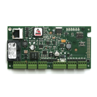
2. MR51e Hardware:
2
3
4 1
S1
S2
123456
ON
J3J7
K1
K2
12V
J5
PoE
J6
TB1 TB2 TB3 TB4 TB5 TB6
11 1 1 1 1
IN1 IN2 IN3 IN4 VO LED BZR CLK DATGND VO GNDDATCLKBZRLED GNDVIN NO NC2-CNONC1-C
J2
0.2 [5.08]
2.35 [59.69]
0.15 [3.81]
2.55 [64.77] 2.55 [64.77]
5.4 [137.16]
STATUS LEDs
2.75 [69.85]
DIP SWITCH
RESET SWITCH
PoE/12Vdc
POWER SELECTOR
JUMPER
ETHERNET RJ45
CONNECTOR
ACTIVITY
(YELLOW)
LINK
(GRREN)
Ø0.125 [Ø3.18]
4 PLACES
1 2 3 4 5 6
VO
VO
IN2
IN1
IN3
IN4
LED
BZR
CLK
DAT
GND
LED
BZR
CLK
DAT
NC
GNDGND
VIN
NO
RLY 1
NO
RLY 2
NC
C
C
TB6
TB5
TB4
TB3
TB2
TB1
J1
6V
5V
3.3V
LNK
ACT
(K1)
(K2)
J4
D24
D19
ETHERNET
STATUS
LEDs
RELAY K1
LED
RELAY K2
LED
STATUS LEDs
SOLDER SIDE