Section 1 - Getting to Know Your Power Package
90-8M0113987 eng DECEMBER 2015 Page 5
•
"OFF" In the "OFF" position, all electrical circuits are off. The engine will not operate with the key switch in the "OFF"
position.
•
"ACC" In the "ACC" position, any accessory connections to the electrical circuits can be operated. The engine will not
operate with the key switch in the "ACC" position.
•
"ON" In the "ON" position, all electrical circuits and instrumentation receive power. The engine can be started with an
optional start stop switch.
•
"START" Turn the key to the start position and release to start the engine.
NOTE: The key can only be removed with the key switch in the "OFF" position.
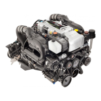
Dual engine start-stop switch
A start‑stop switch is optional equipment. The start‑stop switch works in conjunction with the key switch. There is one start‑stop
switch for each engine. Each button on a multi‑engine start‑stop switch functions independently. The key switch must be in the
run position to start a stopped engine with the the start‑stop switch. Pressing a start‑stop switch button when an engine is
running will shut down the corresponding engine.
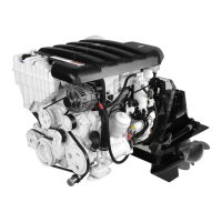
Typical bilge blower toggle switch
Operates the bilge blower, if equipped
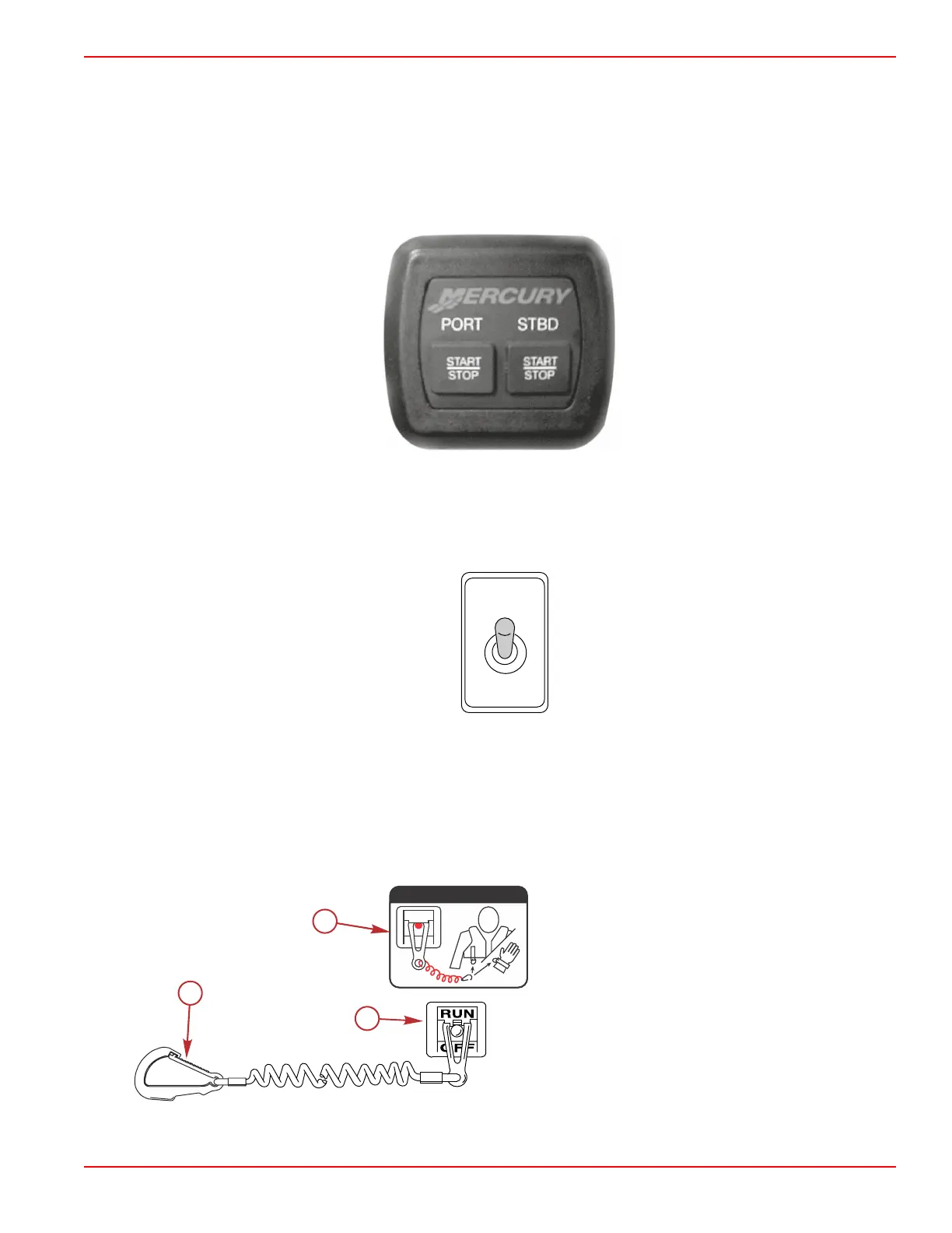
Lanyard Stop Switch
A lanyard switch is designed to shut down the engine in the event the operator unexpectedly moves away from the helm, as
may happen in an accidental ejection. The lanyard is connected to the operator's personal flotation device or wrist.
A decal near the lanyard stop switch reminds the operator to attach the lanyard to his or her personal flotation device or wrist.
a - Lanyard cord clip
b - Lanyard decal
c - Lanyard stop switch
Accidental ejections, such as falling overboard, are more likely to occur in:
c
a
b
53910
OFF
RUN
ATTACH LANYARD
 Loading...