21
90-10212R40
GB
goh89
1
2
3
oh
MAINTENANCE
ohf2
TOP COWL REMOVAL AND INSTALLATION
Removal
1 Unlock the rear latch by pushing lever down.
2 Lift rear of cowl and disengage front hook.
Installation
Engage the front hook and push cowl back over the cowl seal.
Push cowl down and move the rear latch lever up to lock.
omi1
EXTERIOR CARE
3
Your outboard is protected with a durable baked enamel finish. Clean and wax
often using marine cleaners and waxes.
ohn1
BATTERY INSPECTION
The battery should be inspected at periodic intervals to ensure proper engine
starting capability.
IMPORTANT: Read the safety and maintenance instructions which
accompany your battery.
1. Turn off the engine before servicing the battery.
2. Add water as necessary to keep the battery full.
3. Make sure the battery is secure against movement.
4. Battery cable terminals should be clean, tight, and correctly installed. Positive
to positive and negative to negative.
5. Make sure the battery is equipped with a nonconductive shield to prevent
accidental shorting of battery terminals.
goh90
1
ohh7
FUEL SYSTEM
WARNING
Avoid serious injury or death from gasoline fire or explosion. Carefully
follow all fuel system service instructions. Always stop the engine and
DO NOT smoke or allow open flames or sparks in the area while servicing
any part of the fuel system.
Before servicing any part of the fuel system, stop engine and disconnect the
battery. Drain the fuel system completely. Use an approved container to collect
and store fuel. Wipe up any spillage immediately. Material used to contain spillage
must be disposed of in an approved receptacle. Any fuel system service must be
performed in a well ventilated area. Inspect any completed service work for signs
of fuel leakage.
Fuel Line Inspection
Visually inspect the fuel line and primer bulb for cracks, swelling, leaks, hardness,
or other signs of deterioration or damage. If any of these conditions are found, the
fuel line or primer bulb must be replaced.
Fuel Line Filter – Models with Carburetors
1 Inspect the fuel line filter. If the filter appears to be contaminated, remove and
replace.
IMPORTANT: Visually inspect for fuel leakage from the filter connections by
squeezing the primer bulb until firm, forcing fuel into the filter.
goh23
a
c
b
d
1–6
ohh20
FUEL SYSTEM (CONTINUED)
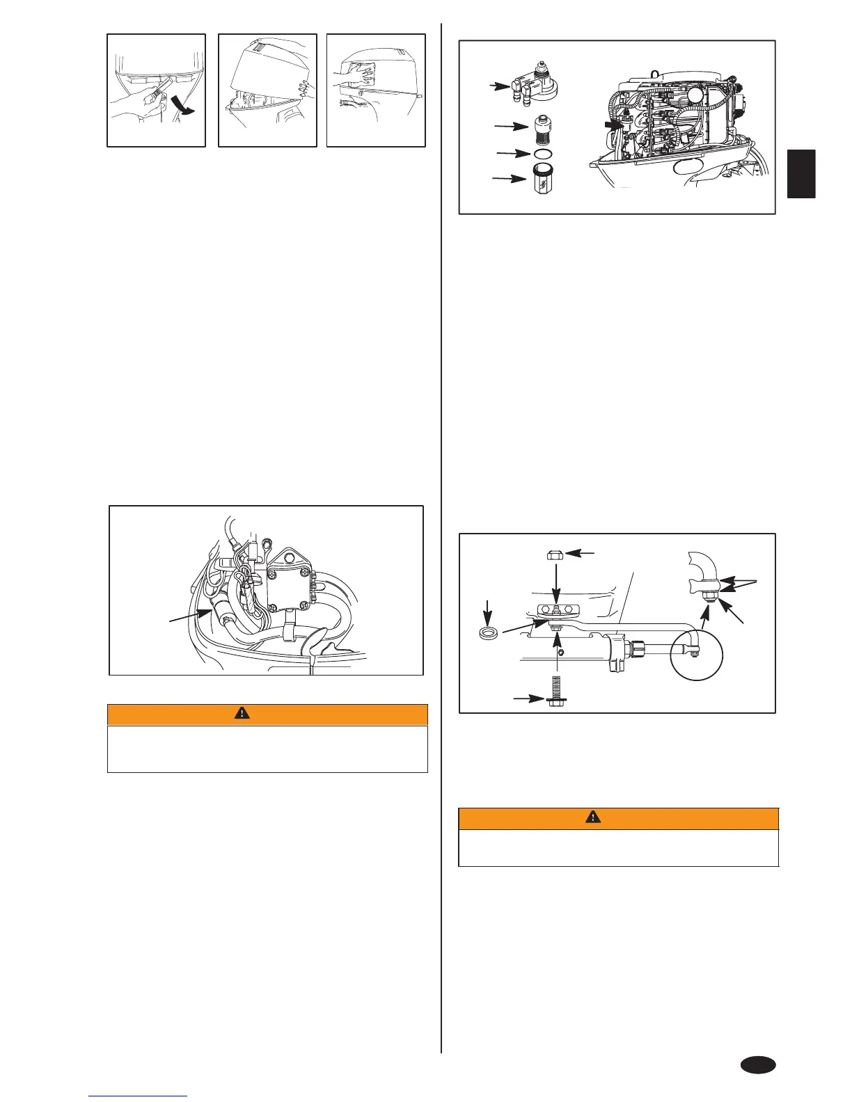
FUEL FILTER – MODELS WITH ELECTRONIC FUEL INJECTION
(EFI)
Check the fuel filter for water accumulation or sediment. If water is in the fuel,
remove the sight bowl (b) and drain the water. If the filter appears to be
contaminated, remove and replace.
REMOVAL
1 Read Fuel System servicing information and Warning on the previous page.
2 Pull out the filter assembly from mount. Hold onto the cover (a) to prevent it
from turning and remove the sight bowl (b). Empty contents into an approved
container.
3 Pull out the filter element (c) and replace it if necessary.
INSTALLATION
4 Push the filter element into the cover.
5 Place the O-ring seal (d) into its proper position on the sight bowl and screw
the sight bowl hand tight into the cover.
6 Push filter assembly back into mount.
IMPORTANT: Visually inspect for fuel leakage from the filter by squeezing
the primer bulb until firm, forcing fuel into the filter.
goh91
a
c
b
d
e
ohi2
STEERING LINK ROD FASTENERS
IMPORTANT: The steering link rod that connects the steering cable to the
engine must be fastened using special washer head bolt (“a” – Part Number
10-90041) and self locking nylon insert locknuts (“b” & “c” – Part Number
11-34863). These locknuts must never be replaced with common nuts (non
locking) as they will work loose and vibrate off, freeing the link rod to
disengage.
WARNING
Disengagement of a steering link rod can result in the boat taking a full,
sudden, sharp turn. This potentially violent action can cause occupants
to be thrown overboard exposing them to serious injury or death.
Assemble steering link rod to steering cable with two flat washers (d) and nylon
insert locknut (“b” – Part Number 11-34863). Tighten locknut (b) until it seats, then
back nut off 1/4 turn.
Assemble steering link rod to engine with special washer head bolt (“a” – Part
Number 10-90041), locknut (“c” – Part Number 11-34863) and spacer (“e” –
12-71970). First torque bolt (a) to 20 lb. ft. (27 N·m), then torque locknut (c) to 20
lb. ft. (27 N·m).
 Loading...