Section 4 - Maintenance
90-8M0113859 eng DECEMBER 2015 Page 63
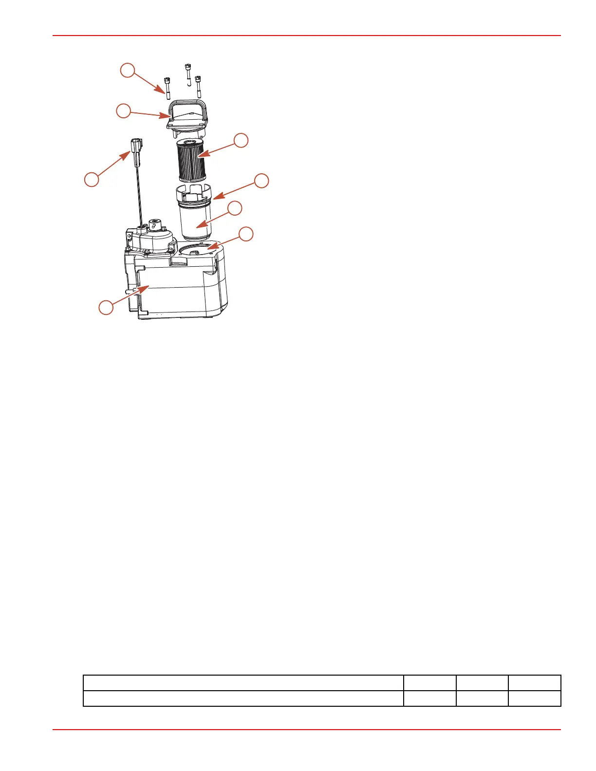
Gen III Models
a - Cool Fuel Module
b - Cool Fuel Module harness
c - Filter cap
d - Filter assembly retaining screw
e - Fuel filter element
f - Filter cup
g - Cool Fuel Module filter reservoir
h - O‑ring
Removal
1. Allow the engine to cool down.
NOTE: Mercury MerCruiser recommends that the engine be shut off for 12 hours prior to filter removal.
2. Close the fuel supply valve, if equipped.
3. Disconnect the Cool Fuel Module harness from the engine wiring harness.
4. Turn the key switch to the start position and allow the starter to operate for five seconds.
5. Turn the key switch to the off position.
6. Loosen each filter assembly retaining screw until the screw is disengaged from the Cool Fuel Module. Do not remove the
filter assembly retaining screws from the filter cap.
7. Unseat the filter assembly by grasping the filter assembly handle and pulling upward. Do not remove the filter assembly
from the Cool Fuel Module at this time.
8. Allow any fuel that may be in the filter assembly to drain out through the bottom of the filter assembly and into the Cool
Fuel Module filter reservoir.
9. Remove the filter cup from the filter cap by grasping the filter cap and rotating it in a clockwise direction while holding the
filter cup stationary.
10. Remove the used water‑separating fuel filter element from the filter cup, place it in a clean, approved container.
11. Dispose of any water or debris that may be in the filter cup.
Installation
1. Install a new water‑separating fuel filter element into the filter cup. Push the element into the cup until completely seated.
2. Install a new O‑ring on the filter cup.
3. Attach the filter cap to the filter cup by grasping the filter cap and rotating it in a counterclockwise direction while holding
the filter cup stationary, until the filter cap locks securely into place.
4. Install the fuel filter assembly slowly into the Cool Fuel Module to prevent spilling fuel, and align the screws retained in the
filter cap with the screw holes in the Cool Fuel Module. Tighten the filter assembly retaining screws until hand‑tight.
5. Ensure that the filter cap is firmly seated against the Cool Fuel Module and torque each filter assembly retaining screw.
Description
Nm lb‑in. lb‑ft
Filter assembly retaining screw 6 53 –
d
a
b
c
e
f
g
h
8837
 Loading...


