CHARGING SYSTEM
90-857138R1 MAY 2000 Page 2B-7
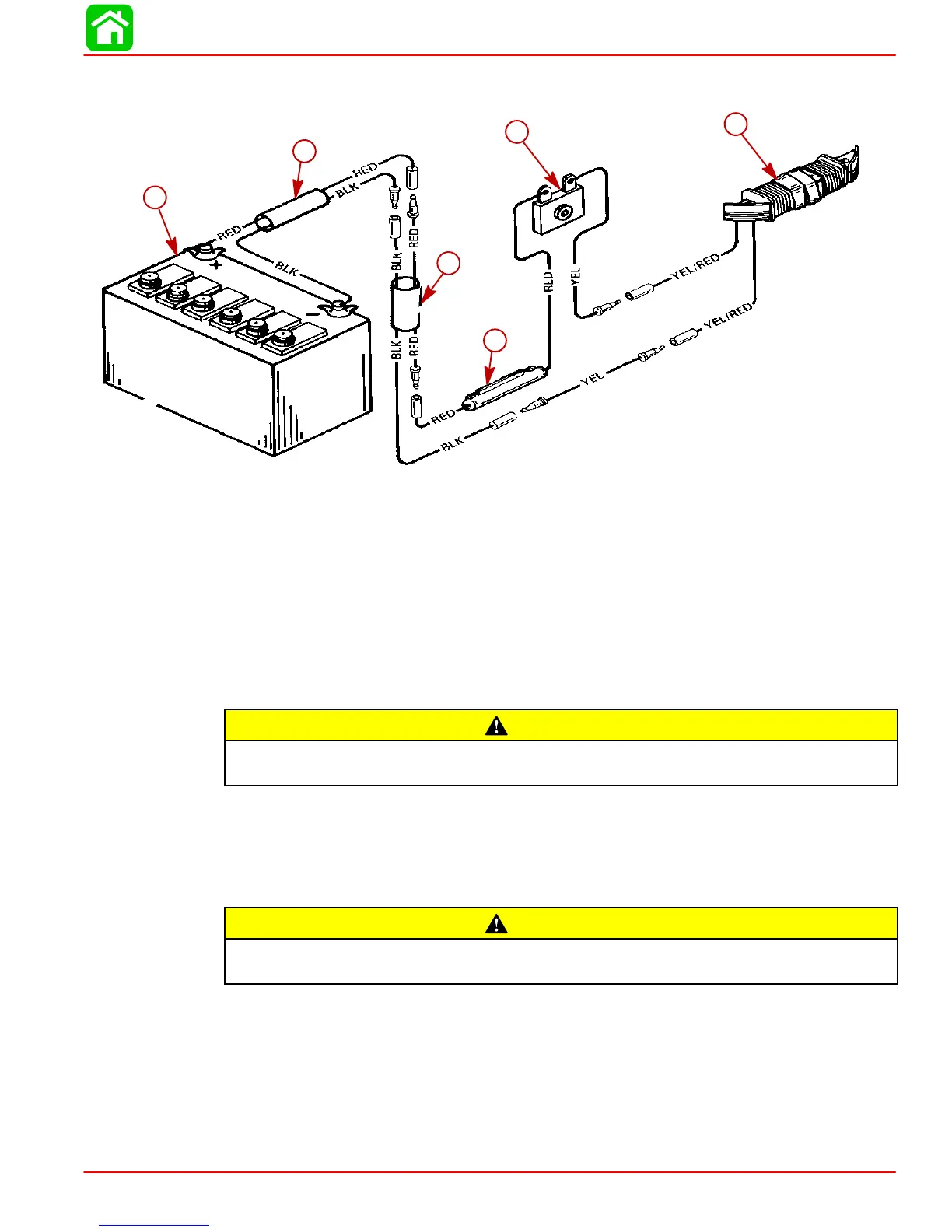
6. Make all wiring connections, as shown in wiring diagram “A”.
b
c
d
e
f
a
WIRING DIAGRAM “A” Rectifier Kit Installation
a-Alternator Kit (16837A2)
b-Rectifier
c-Fuse Holder with 10 Amp Fuse
d-Extension Harness - 22 in. (56 cm) Long
e-Battery Harness - 69 in. (175 cm) Long
f-Battery
Battery Connections
CAUTION
Failure to observe correct polarity when connecting battery harness leads to bat-
tery, will result in damage to the charging system.
House battery in a battery box and secure in a favorable position in boat.
Connect red battery harness lead to positive (+) battery terminal and black battery harness
lead to negative (–) battery terminal.
Special Operating Instructions
CAUTION
Disconnect both (2) yellow/red alternator leads (refer to Wiring Diagram “A”) before
operating outboard motor without battery harness leads connected to battery.
 Loading...