Do you have a question about the Mercury 4 SERIES and is the answer not in the manual?
| Starting | Manual |
|---|---|
| Cylinders | 1 |
| Fuel Type | Gasoline |
| Steering | Tiller |
| Recommended Fuel | 87 Octane |
| Warranty | 3 years |
| Horsepower | 4 HP |
| Full Throttle RPM | 5000 - 6000 RPM |
| Alternator Output | Not Available |
| Fuel System | Carburetor |
| Cooling System | Water Cooled |
| Shaft Length | 15 in |
| Gear Shift | Forward, Neutral |
Schedule outlining required inspections and maintenance tasks based on hours or time.
Information and procedures related to the fuel system, including inspection.
Step-by-step procedure for changing the engine oil, including capacity and filling.
Procedure for draining, inspecting, and filling the gear case lubricant.
Explanation of detonation in a 4-cycle engine, its causes, and prevention methods.
Guidelines for selecting the correct propeller for optimal engine performance and durability.
Step-by-step instructions for removing and installing the outboard propeller.
Procedure for checking cylinder compression to diagnose engine wear or performance issues.
Step-by-step instructions for mounting the outboard motor onto the boat transom.
Procedures for testing the ignition system using ohmmeters and voltage testers.
Procedures for removing and installing ignition system components.
Procedures for removing and installing the ignition coil.
Procedures for removing and installing the CDI unit.
Information on ignition timing, noting it is fixed and cannot be adjusted.
Procedure for checking ignition timing at idle and wide-open throttle using a timing light.
Schematic diagram showing electrical connections for the outboard motor components.
Step-by-step procedures for removing and installing the fuel pump.
Procedures for adjusting the carburetor's idle speed and pilot mixture screw.
Procedure for adjusting the pilot mixture screw for optimal idle performance.
Procedure for adjusting the engine's idle speed.
Step-by-step instructions for removing and installing the carburetor.
Exploded view and parts list for the cylinder block assembly.
Exploded view of intake and exhaust valves, their components, and related service aids.
Procedure for checking and adjusting valve clearance while the engine is cool.
Exploded view and parts list for the crankshaft assembly.
Exploded view and parts list for the oil pan assembly and its components.
Procedure for removing the powerhead from the drive shaft housing.
Steps for installing the reassembled powerhead onto the drive shaft housing, including component reassembly.
Exploded view and parts list for the driveshaft housing assembly.
Exploded view and parts list for the clamp brackets and swivel bracket.
Procedures for reassembling the clamp bracket and swivel bracket components.
Procedures for installing the drive shaft housing into the swivel bracket.
Specifications for the gear housing, including ratio, capacity, and lubricant type.
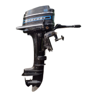
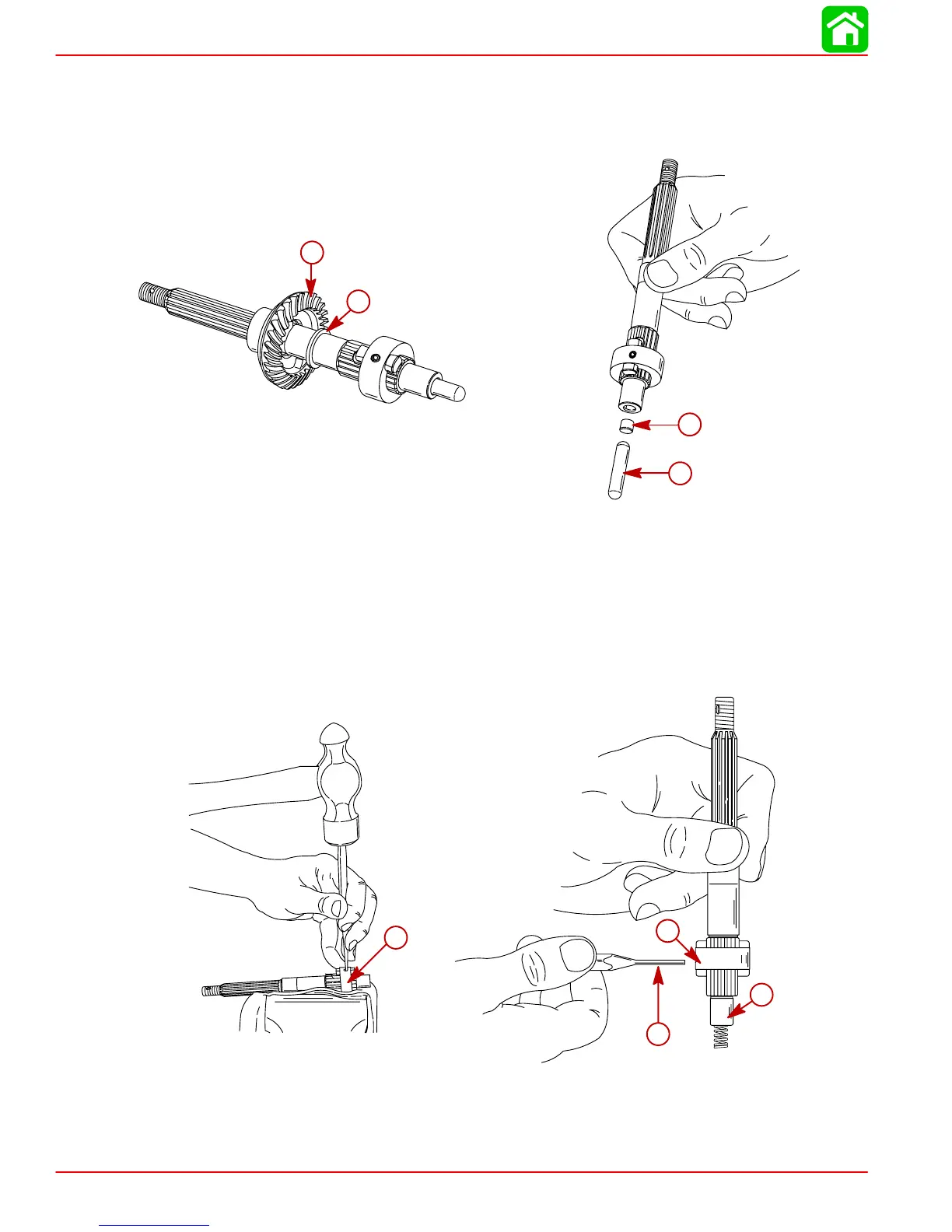
Exploded view and parts list for the drive shaft portion of the gear housing.
Exploded view and parts list for the propeller shaft portion of the gear housing.
Procedure for draining, inspecting, and checking the gear housing lubricant for contamination.
Safety precautions and steps for removing the propeller.
Procedure for removing the gear housing from the drive shaft housing.
Procedure for installing the gear housing, including safety precautions and shift shaft alignment.
Step-by-step instructions for installing the propeller onto the propeller shaft.
Procedure for filling the gear housing with Quicksilver Gear Lube, including plug removal and installation.
Exploded view and parts list for the shift linkage components.
Procedures for removing and disassembling the shift linkage components.
Procedures for lubricating and installing the shift linkage components.
Exploded view and parts list for the steering handle assembly.
Exploded view and parts list for the recoil starter assembly.
Steps for removing the manual starter assembly from the engine.
Procedure for installing the rewind starter assembly onto the engine.
Detailed steps for disassembling the rewind starter, emphasizing spring tension safety.
Procedures for reassembling the rewind starter components, including lubrication.