Mercury Security Corporation, © 2008 BR20 Doc. 10107-0024 rev. 1.03 10/2008 Page 2
Information subject to change without notice.
The reader is rated to operate over an extended
temperature range and the electronics are conformal
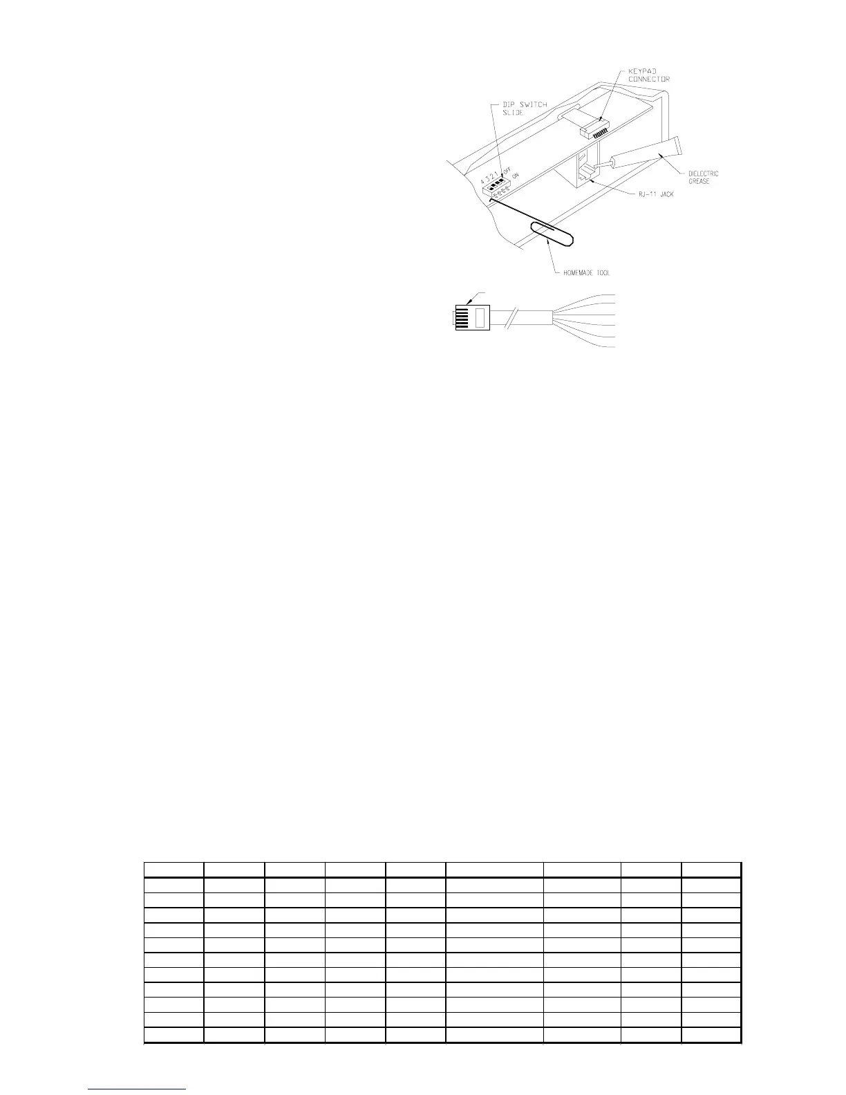
coated against moisture. If the reader is expected to
be exposed to weather, use the dielectric grease to
coat the field connections. After field connection/
configuration is made, the grease is to be applied on
the DIP switch slides, keypad connection, and the
RJ-11 jack to seal out moisture.
Do not use sealant to seal reader case to the
wall. Doing so will trap water in the reader and may
cause damage to the reader.
6. TTL Interface:
The TTL interface has the standard 5-wire interface widely used in the access control application. In addition, an input
to control the buzzer is provided. Cable with minimum of 24AWG wires should be used.
Pin # Wire Signal Description
1 Red Vin Power supply input, 5Vdc or 12Vdc, Model dependent
2 Green /Data (Mag) or Reader data output
/Data 0 (Wieg)
3 White /Clock (Mag) or Reader data output
/Data 1 (Wieg)
4 Brown LED LED input
1-wire control: 0V turns on the green LED
5V turns on the red LED
2-wire control: 0V turns on the red LED
5 Orange Buzzer/LED Buzzer/LED input
1-wire control: 0V turns on the buzzer
2-wire control: 0V turns on the green LED
6 Black Signal Ground Power supply return, DC ground
7. Grounding the Reader:
To avoid having ESD (electrostatic discharge) interfering with the operation of the reader, the reader casing shall be
grounded. This can be accomplished by tying the mounting bracket to earth ground locally (e.g. grounded conduit).
8. DIP Switch Setting:
The DIP switch on the BR20 reader is used to select a preset format, the functions for the LED and buzzer, and the
output signal format, etc. The preset format determines how the card is interpreted. Refer to the format specification
for detail. The settings are for STANDARD models ONLY. The BR20 does not support the tamper switch option.
MODULAR PLUG
1 (RED) +5 or +12Vdc
2 (GRN) DATA 0/DATA
3 (WHT) DATA 1/CLOCK
4 (BRN) LED
5 (ORG) BUZZER/LED
6 (BLK) GND
depends on model
FORMAT SW-4 SW-3 SW-2 SW-1 OUTPUT LED BUZZER TAMPER
0 ON ON ON ON DATA 1/DATA 0 1-WIRE LED YES NO
1 ON ON ON OFF CLOCK/DATA 1-WIRE LED YES NO
2 ON ON OFF ON CLOCK/DATA 1-WIRE LED YES YES
3 ON ON OFF OFF CLOCK/DATA 1-WIRE LED YES NO
4 ON OFF ON ON DATA 1/DATA 0 1-WIRE LED YES NO
5 ON OFF ON OFF DATA 1/DATA 0 1-WIRE LED YES NO
6 ON OFF OFF ON DATA 1/DATA 0 1-WIRE LED YES NO
7 ON OFF OFF OFF DATA 1/DATA 0 1-WIRE LED YES NO
12 OFF OFF ON ON CLOCK/DATA 2-WIRE LED NO NO
13 OFF OFF ON OFF DATA 1/DATA 0 2-WIRE LED NO NO
15 OFF OFF OFF OFF CLOCK/DATA 1-WIRE LED YES YES
 Loading...