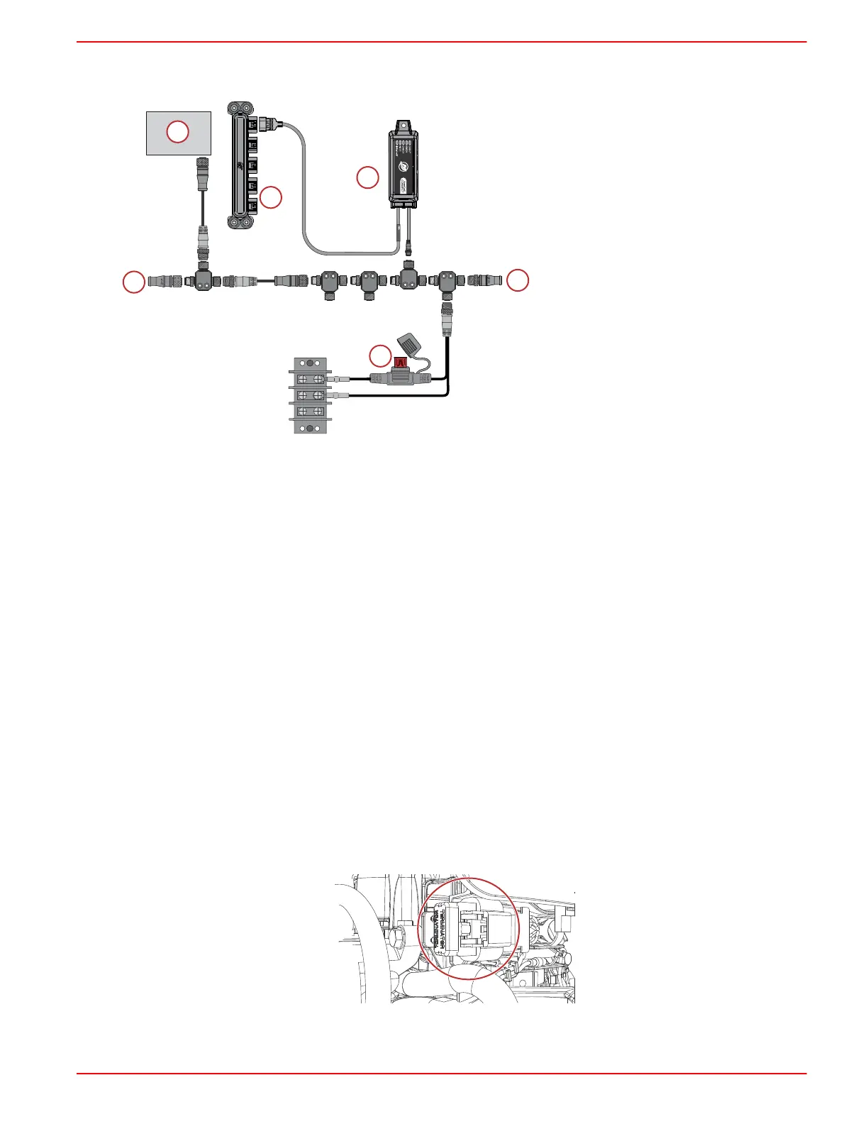
2. Connect the module NMEA 2000 harness connector to the NMEA 2000 network. A NMEA 2000 extension may be
required to reach the NMEA 2000 backbone.
a - 120‑ohm termination resistor
b - Chartplotter
c - SmartCraft CONNECT module
d - NMEA 2000 fused power source
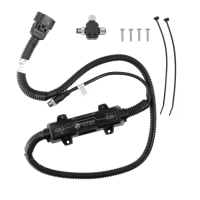
e - SmartCraft junction box
On‑Engine Mounting Guidelines
Mounting Requirements
NOTE:The 10‑pin on‑engine terminator must be removed from the engine harness before installation of the module.
• The SmartCraft CONNECT module must be mounted in a location that allows for connection to the 10‑pin connector on
the engine harness. No additional 10‑pin harnessing may be used in the installation of this product.
• All routing must adhere to harness installation bend parameter specifications. The minimum bend radius of any portion of
the harness must be no less than 13 mm (0.5 in.).
• Two cable ties to secure the SmartCraft CONNECT module must be used to prevent unwanted movement during normal
operation of the propulsion package.
•
The following locations must be avoided when installing the SmartCraft CONNECT module.
• Any location which can be exposed to water
• Any location that is subject to high heat during operation of the power package
• Near ignition coils
• Near spark plug wires
• Near shift/throttle cables
• Where harnessing could contact belts
• Secured to fuel lines
25/30 FourStroke EFI On‑Engine Mounting
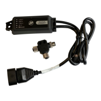
1. Locate the SmartCraft 10‑pin connector and remove the CAN termination resistor. Connect the 10‑pin connector on the
SmartCraft CONNECT harness. On‑engine modules are internally terminated, so the termination resistor is no longer
needed.
71914
e
c
TERMINATED
ENGINE MOUNT ONLY
SCC-1 SMARTCRAFT CONNECT GATEWAY INSTALLATION MANUAL
90-8M0219240 eng MAY2023 © 2023 Mercury Marine Page3 / 23
 Loading...