7 NE 72 en 5
2 MOUNTING ON THE METSO ACTUATOR
2.1 General
When the positioner is supplied together with the valve and
actuator, the tubes are mounted and the positioner adjusted in
accordance with the customer's specifications.
When the positioner is ordered separately, the mounting parts
for the assembly must be ordered at the same time.
Example order: Positioner alone (BC12)-Z-NE724.
The positioner is equipped with VDI/VDE 3845 (S1) mount-
ing face. This mounting face requires a shaft with the H cou-
pling.
Old Metso Automation style mounting face code S2 is no
more available.
For mounting parts for Metso actuators, see Sections 13.2 -
13.3.
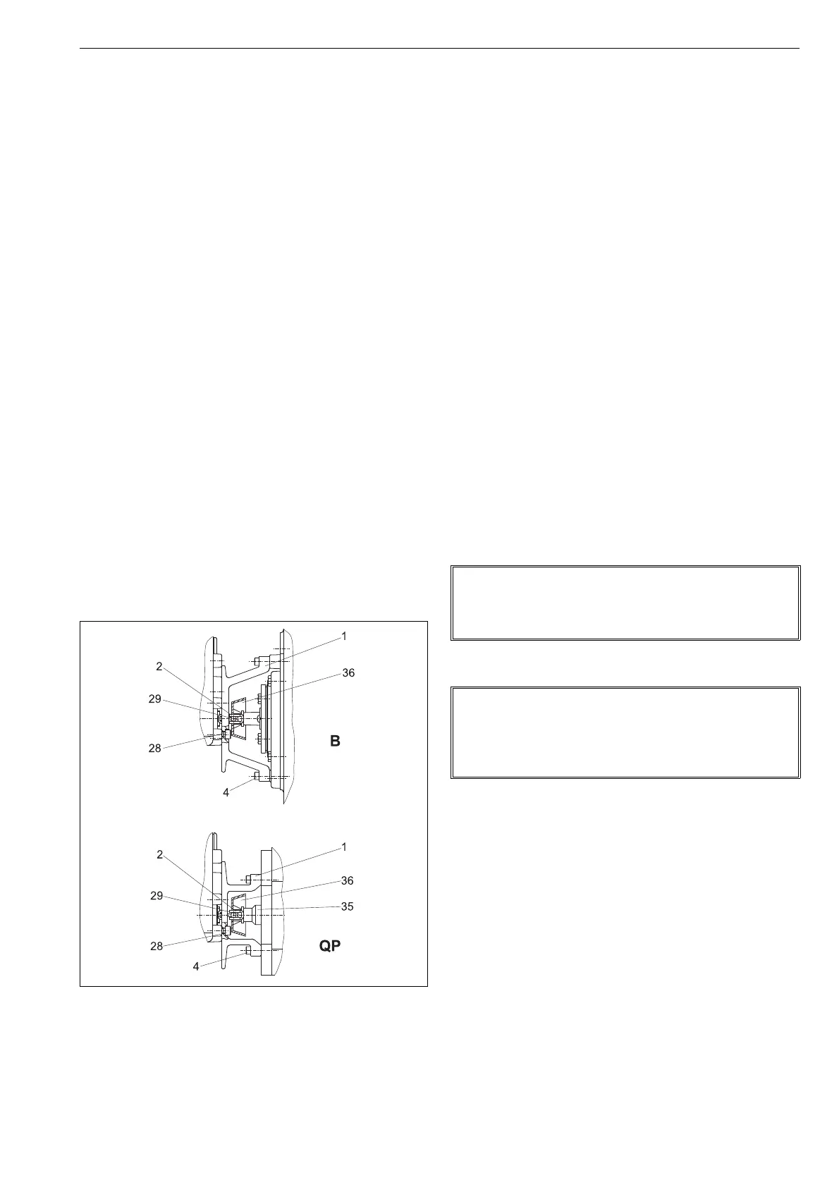
2.2 Installing positioner NE700/S1 on
Metso actuators with VDI/VDE 3845
mounting face
1. The actuator piston must be in the up position (in spring-
return actuators as determined by the spring).
2. Install the pointer (only B_U) parallel with the valve clo-
sure member and fasten the draught piece (2) with a
screw (29) to the pointer cover (B_U) or to the coupling
(QP), as shown in Fig. 5. Secure the draught piece fasten-
ing screw with a sealant (e.g. Loctite) and tighten it
properly.
3. Fasten the mounting bracket (1) to the positioner.
4. Fasten the mounting bracket (1) to the actuator.
2.3 NE_700/700 positioner/limit switch
combination (Obsolete since 2013)
The bottom of the limit switch acts also as the cover for the
positioner. Remove the limit switch before the adjustment
of the positioner.
1. Loosen the cover screws. Note the position of the shaft
relative to the positioner when removing the limit switch.
2. When the adjustment of the positioner is done, operate
the actuator until the valve is in the closed or open posi-
tion.
3. Note the position of the actuator and valve when
mounting the limit switch on the actuator. Make sure
that the position of the shaft is unchanged relative to
the positioner.
4. Place the limit switch on the positioner so that the
shafts are correctly engaged.
5. Fasten the cover screws.
6. Check the adjustment of the limit switch. See the
instruction manual of the limit switch for details.
2.4 Piping of supply air
Table 2 provides the recommended pilot valve and tube
sizes in accordance with the actuator sizes. Tube sizes are
minimum values allowed.
Connect air supply to S (1/4 NPT).
Connect C1 and C2 (1/4 NPT) to the actuator according to
Fig. 6.
See also Chapter 3.
For pipe threads are liquid sealants, e.g. Loctite, recom-
mended.
Fig. 4 Installing on a Metso actuator (S1)
NOTE:
A single action connection alone is permitted for position-
ers mounted on the spring actuator!
Place a plug in connection C1 or C2. See Figure 6.
NOTE:
Exessive sealant may cause faulty operation of the posi-
tioner.
Sealing tape is not recommended.
Ensure the cleaness of the air piping.
 Loading...