8 7 NE 72 en
2.5 Instrument air supply
The supply air must be clean, dry and oil-free instrument air,
e.g. according to standard ISA S7.3–81. Supply pressure is
1.4–8 bar (20–115 psi).
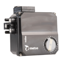
2.6 Electric connections
The input signal cable is lead trough a PG11 cable gland to
the housing. Connect the conductors to the terninal on the
terminal card, plus (+) and minus (-) accordingly. See Fig. 7.
The wiring schematic is shown in Fig. 8.
3 INPUT SIGNAL AND DIRECTIONS OF
OPERATION
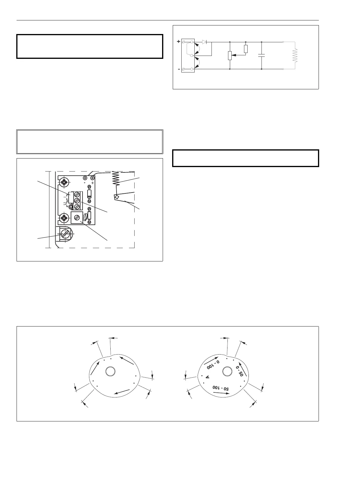
Figure 6 assists in choosing the right segment for the cam
plate (29) and position for the changeover piece (46).
3.1 Changeover piece
The function of connection C1 and C2 can be altered by
turning the changeover piece (46). The diagram D (or R)
shown on the protective plate (48) functions when the sym-
bol D (or R) is visible in the lower lefthand corner of the
changeover piece. D = direct, R = reverse.
External changes in the tubes are not needed. Positioner
NE727 is an exeption (DIA6HC pilot valve). Then the
changeover piece must always be in position R and the
external tubes mounted in accordance with Fig. 6.
3.2 Cam plate
The figures marked on the cam plate (29) are the signal
ranges expressed as percentages, for example 0–100 corre-
sponds to 4–20 mA, or 50–100 to 12–20 mA. See Fig. 9.
The arrows on the cam plate show the direction it must turn
when the input signal is rising in the cam segment in ques-
tion.
The non-rising segments between the rising segments are
roughly 15°–20°.
CAUTION:
Do not exceed the permitted actuator supply air pres-
sure!
NOTE:
The wires should not be led through the operational area
of the feed-back lever (33) and feed-back spring (41).
Fig. 6 Terminal card
feed-back
spring (41)
feed-back
lever (33)
earth
connection
range adjustments
terminal
jumper
Fig. 7 Wiring schematic
CAUTION:
Do not dismantle a pressurized positioner!
I
U
1000 W
CCW
CW
220 W
47 mF
Rk=220 W
Fig. 8 Input signal ranges
~ 15°
~ 15°
~ 15°
~ 15°
~ 15°
~ 15°
4...12 mA/0...10 mA/10...30 mA
rising signal closes
segment C
segment E
segment D
segment C
segment E
4...12 mA/0...10 mA/10...30 mA
rising signal opens
4...20 mA/0...20 mA/10...50 mA
rising signal opens
4...20 mA/0...20 mA/10...50 mA
rising signal closes
12...20 mA/10...20 mA/30...50 mA
rising signal closes
12...20 mA/10...20 mA/30...50 mA
rising signal opens
 Loading...