7 NE 72 en 9
4 PRELIMINARY ACTIONS FOR THE
ADJUSTMENT
Set the valve's open and closed limits with the actuator lim-
iter screws; see the valve instruction manual. The changeo-
ver piece (46), the cam (29) and the internal feed-back
spring (40) must be in correct positions. Check the pilot
valve size from Table 2.
The adjustment must always be carried out when the sup-
ply pressure has been changed.
Please note that operating of the valve is required during
the adjustment.
4.1 Position of the changeover piece
Choose the position of the changeover piece, D or R, from
Fig. 6 in accordance with the function desired.
Turn the changeover piece (46) when necessary.
Loosen the nuts (49) and remove the protective plate (48).
Pull out the changeover piece (46). Check the O-rings (47,
2 pcs.) and apply silicone grease lightly if needed. Place the
changeover piece (46) and the protective plate (48) in the
case. Tighten the nuts (49) evenly, one after the other.
4.2 Pilot valve
Removal of the pilot valve is unnecessary when the change-
over piece is turned around. For instructions of removal, see
Section 8.2.
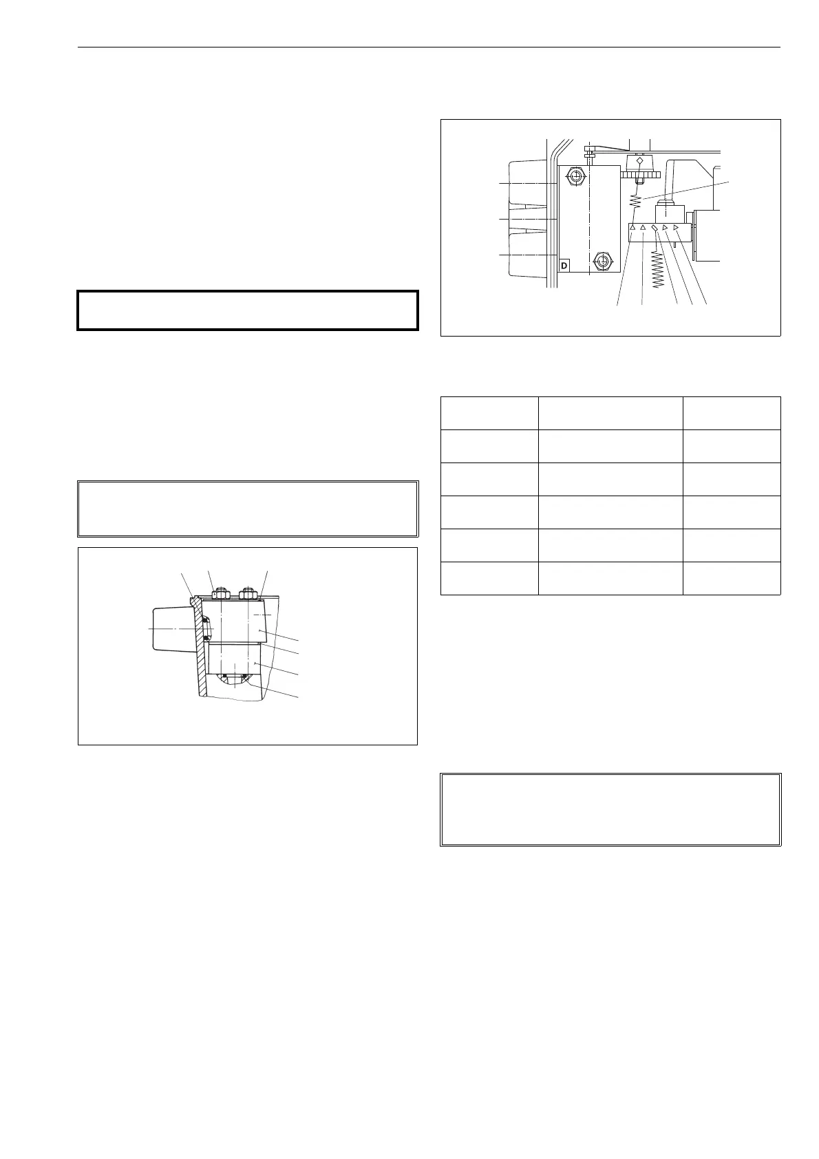
4.3 Setting the internal feed-back spring
Select the position for the lower end of the spring (40) from
Table 3 in accordance with the actuator size. The spring set-
ting must be made before the zero adjustment of the posi-
tioner, as it affects the adjustment.
The amplification of the positioner increases as the spring
(40) is moved from position 'a' to position 'e'.
If in the field the valve overshoots, the spring (40) can be
moved to the 'a' direction. If the valve goes into position too
slowly the spring can be moved to the 'e' direction respec-
tively.
In sticker inside the cover (2) has also been shown the posi-
tion for the lower end of the spring (40) in accordance with
the actuator size.
4.4 Position of the cam plate
Choose the side, A or B, and the rising segment of the cam
plate from Fig. 6 in accordance with the function desired.
Move the actuator piston to the end where the input signal
has its lower value. Shut off the supply pressure or move the
pilot spool by deflecting the balance beam (164) gently so
that the piston strokes to the desired limit. The input signal
should be zero or at the lower limit.
Loosen the screw (57), remove the indicator (32), loosen the
screw (31) and the locking wheel (30). Turn the cam plate
(29) to the desired side.
In case of α
0
adjustment, proceed acc. to Sections 6.1 and
6.2.
Place the roller so that its contact point is 1 mm from the
beginning of the rising segment. Then tighten the locking
wheel (30) and the screw (31).
CAUTION:
Do not dismantle a pressurized positioner!
NOTE:
Check that the changeover piece is mounted correctly:
Symbol D or R is visible in the lower left hand corner.
Fig. 9 Mounting the changeover piece
Fig. 10 Setting the internal feed-back spring
Table 3 Setting the internal feed-back spring
Spring (40)
setting
Actuator size
Cylinder volume
dm
3
a B1C 6, 8, B1J 6
QP 1
<0,5
b B1C 9, 11, 12; B1J 8
QP 2 (QP 1 *)
0,5...1
c B1C 13, 16; B1J 10, 12
QP 3 (QP 2 *)
1...4
d B1C 17, 20, 25; B1J 16
QP 4, QP 5 (BJ 8 *)
4...11
e B1C 32, 40; B1J 20, 25
B1C 50, 502; B1J 32, 322
11...50
*) NE729S positioner, (Obsolete since 2013).
NOTE:
Don't move the pilot spool by deflecting the beam (5).
The double diaphragm keeps the beam steadfast in the
position.
 Loading...