LEOPARD OPERATING INSTRUCTIONS
19
CHAPTER 3: AMPLIFICATION AND AUDIO
LEOPARD’s drivers are powered by a proprietary three-
channel, open-loop, class D amplifier. The audio signal is
processed with an electronic crossover plus correction filters
for flat phase and frequency responses, and by driver
protection circuitry. Each channel has peak and rms limiters
that prevent driver over-excursion and regulate voice coil
temperatures.
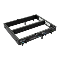
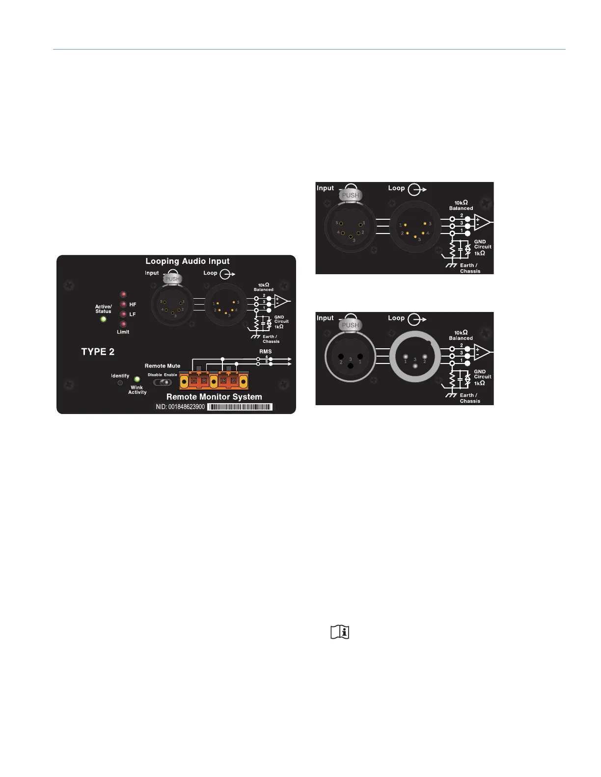
The LEOPARD user panel (Figure 13) includes Input and Loop
output connectors for audio, Limit and Active LEDs, and RMS
connectors and controls (see Chapter 5, “RMS Remote
Monitoring System”).
AUDIO CONNECTORS
LEOPARD is available with XLR 3-pin or 5-pin connectors
for audio Input and audio Loop output (Figure 14 and
Figure 15). XLR 5-pin connectors accommodate both
balanced audio and RMS signals.
Audio Input (XLR 3-Pin or 5-Pin Female)
The XLR 3-pin or 5-pin female Input connector accepts
balanced audio signals with an input impedance of
10 kOhm. The connector uses the following wiring scheme:
• Pin 1 — 1 kOhm to chassis and earth ground (ESD
clamped)
• Pin 2 — Signal (+)
• Pin 3 — Signal (–)
• Pin 4 — RMS (polarity insensitive)
• Pin 5 — RMS (polarity insensitive)
• Case — Earth (AC) ground and chassis
NOTE: Pins 4 and 5 (RMS) are included only
with XLR 5-pin connectors.
Figure 13: LEOPARD User Panel
Figure 14: XLR 5-Pin Audio Connectors, Input and Loop Output
Figure 15: XLR 3-Pin Audio Connectors, Input and Loop Output

 Loading...