8
PSM-2 and PSW-2
The PSM-2 can be used with the Meyer PSW-2, PSW-4,
or 650-P self-powered subwoofers. However, due to the
overlap of frequency response between the PSM-2 and
the subwoofer, the system frequency response exhibits a
rise in the range 50–120 Hz. The rise can be eliminated
by the Meyer CP-10 Parametric Equalizer, if desired.
In a close-proximity coplanar orientation, set the PSM-2
and a Meyer self-powered subwoofer to the same
polarity. Although it is preferable to use the PSM-2
with a self-powered sub, the Meyer 650-R2, USW-1,
and MSW-2 externally amplified subwoofers can
also be used if the sub’s amplifier and the PSM-2 are
set to opposite polarities.
Although the 90° angle is often used for the PSM-2
with a sub, the best angle to use depends on the
musician’s height and distance from the monitor and
whether the musician is standing or seated.
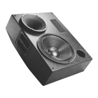
CP-10 EQ
(1 Channel)
input
loop
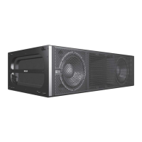
PSW-2
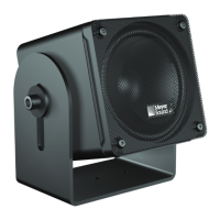
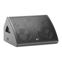
PSM-2
Set the PSM-2 and PSW-2 to the same polarity. All Meyer
self-powered speakers have a loop connection on the user
panel that can send the input signal to another speaker.
Verifying Polarity
Incorrect driver polarity impairs system performance
and may damage the drivers. Every PSM-2 is shipped
with the drivers in correct alignment. However, if the
driver or circuit wiring has been removed or disassembled
for any reason, check the polarity between adjacent
monitors and between drivers in the same monitor.
Polarity Between Adjacent PSM-2s
It is essential that two PSM-2s used together have the
same polarity. Use the following test procedure to
verify the polarity between adjacent PSM-2s:
1. Position two PSM-2s adjacent to each other.
2. Place a measurement microphone 6 feet from the
monitors on the axis between them.
3. Connect a signal source to one PSM-2 and note
the frequency response and overall level.
4. Apply the same signal to the second PSM-2 with
the first still connected.
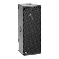
Correct polarity causes
acoustic addition
Opposite polarity cause
acoustic cancellation
Top view of adjacent PSM-2s
with measurement microphone
The polarity is correct if the frequency response remains
constant with a significant increase in amplitude.
Broadband cancellation (decreased overall level)
indicates polarity reversal.
Driver Polarity in the Same PSM-2
Use the following test procedure to verify polarity
between drivers in the same PSM-2:
1. Place a monitoring microphone 3 feet from the
front of the monitor at the midway point between
the high and low frequency drivers.
2. Connect a signal source to the PSM-2 and note
the frequency response.
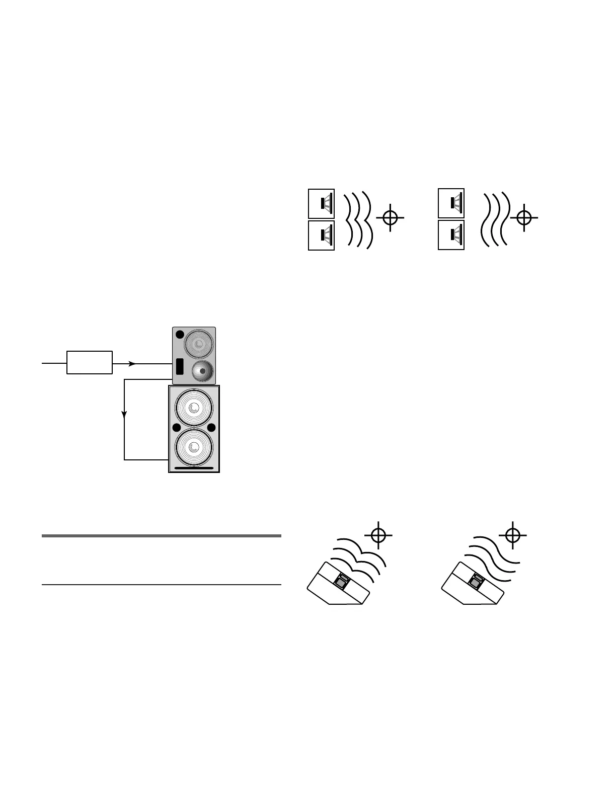
NOTE: Since polarity reversal causes excessive driver
excursion at high source levels, use moderate levels
when conducting this test.
Drivers with correct
polarity cause acoustic
addition
Drivers with reverse
polarity cause acoustic
cancellation
The polarity is correct if the frequency response is smooth
through the crossover region (±4 dB 600 Hz–1 kHz).
Severe cancellation in the crossover region indicates
polarity reversal.
 Loading...