32808001101 13
Specifications subject to change without notice.
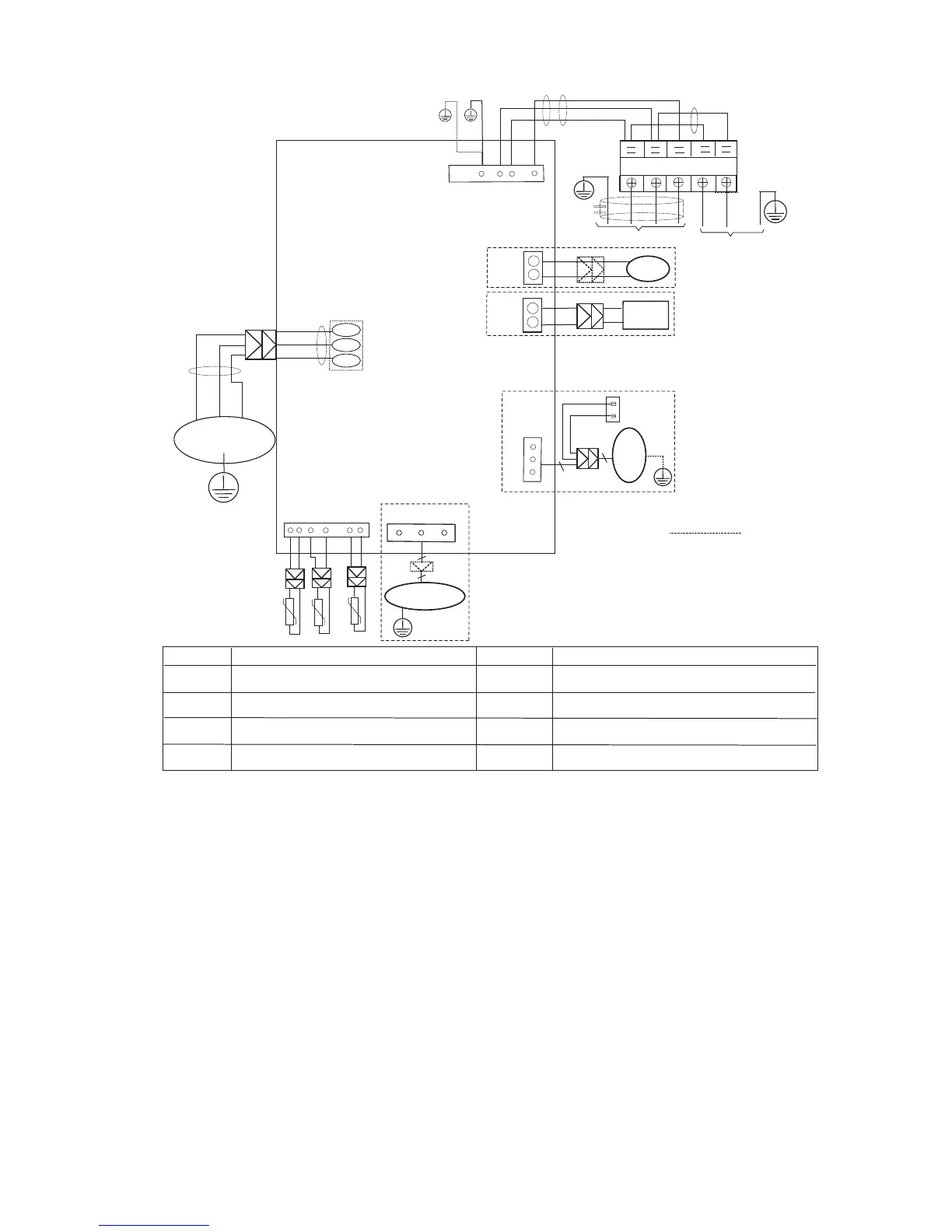
WIRING DIAGRAMS (CONTINUED)
4-WAY
DC-FAN
OPTIONAL:
DC-FAN
CN 414
3
CN 60
OPTIONAL
CRANKCASE
HEATER
CN 16
OPTIONAL
AMBIENT TEMP
. SENSOR
DISCHARGE TEMP. SENSOR
CN 17
CONDENSER TEMP.
SENSOR
Y/G
OUTDOOR
MAIN
PCB
BLUE
BROWN
BLACK
,1'22581,7
S
L2
L1
L2
32:(56833/<
RED
BLUE
L1
Y/G
Y/G
CN 3
Y/G
Y/G
Y/G
OPTIONAL
$&)$1
CAPACITOR
OPTIONAL:
AC-F
AN
5
3
CN 5
Y/G
L1
L2
73
7
7
Notes:
This symbol indicates
the element is optional,
the actual shape shall
prevail.
S
Yellow
Red
Blue
According to the real objects
COMPRESSOR
BLUE
BLACK
CN 21
CN 29
CN 28
CN 27
BLUE
RED
BLACK
W
V
U
&2'(
&1
&1
&1
&2'(
&1
&1
&1
3$571$0( 3$571$0(
Input: 220V high voltage connector with
L1/L2/signal/ground
Output: 0~320VDC to control DC FAN
Output: PWM for UVW to control
Compressor(0~320VAC)
Output: 220V AC to control crankcase heater
Output: 0~220V AC to control 4-way valve
Input: Temperature acquisition(0-5VDC)
RED
&1
Output: 0~220VAC to control AC FAN
Fig. 10 - Wiring Diagram Sizes 18K − 24K (Cooling Only Units)
 Loading...