14
CAUTION
■ Ensure that return water to the heat exchanger does not exceed 60°C. Never put the target water flow temperature set point on the
user interface above 60°C.
■ Make sure that the non-return valves (field supply) are correctly installed in the system.
■ The supplier will not be held liable for any damage resulting from failure to observe this rule.
■ During heating operation of the boiler, the boiler will operate to achieve the target water flow temperature set on the user interface.
■ Never set the target water flow temperature set point on the user interface above (60°C).
Make sure to correctly configure FOR SERVICEMAN in the user interface. Refer to 10.7 Field settings/Other heating source.
NOTE
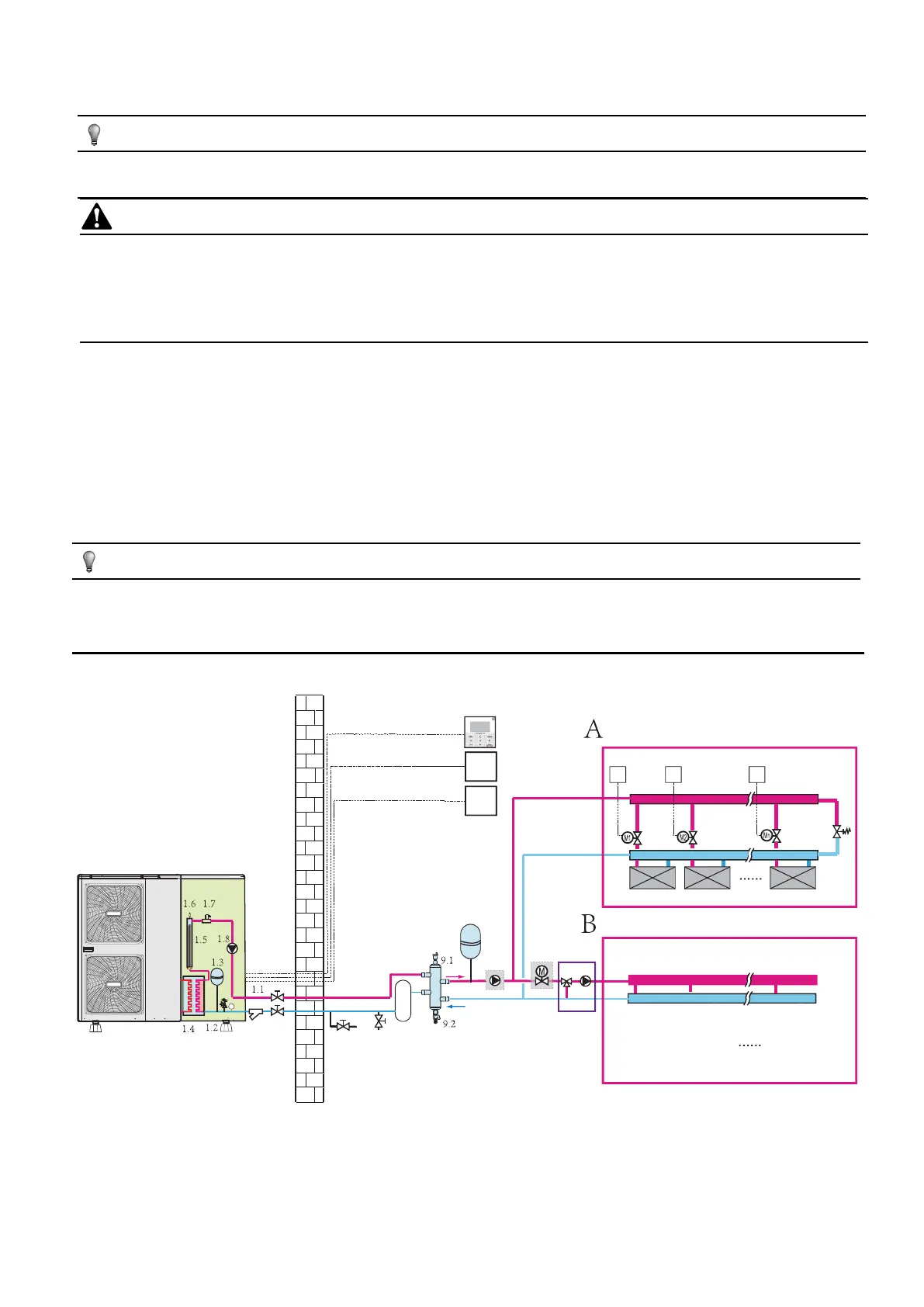
8.6 Application
■ Space heating with two room thermostat application through floor heating loops and fan coil units. The floor heating loops and fan coil units
require different operating water temperatures.
■ The floor heating loops require a lower water temperature in heating mode compared to fan coil units. To achieve these two set points, a
mixing station is used to adapt the water temperature according to requirements of the floor heating loops. The fan coil units are directly
connected to the unit water circuit and the floor heating loops are after the mixing station. Control of this mixing station is not done by the unit.
■ The operation and configuration of the field water circuit is the responsibility of the installer.
■ We only offer a dual set point control function. This function allows two set points to be generated. Depending on the required water
temperature (floor heating loops and/or fan coil units are required) the first set point or second set point can be activated. See 10.7 field setting
/ROOM THERMOSTAT.
NOTE
The wiring of room thermostat 5A(for fan coil units) and 5B(for floor eating loops) should follow 'method C' as described in 9.6.6
Connection for other components/For room thermostat, and the thermostat which connect to port 'C' (in the outdoor unit) should be
placed on the zone where floor heating loops is installed(zone B), the other one connect to port 'H' should be placed on the zone
where fan coil units is installed(zone A).
FHL1 FHL2 FHLn
FCUnFCU2FCU1
T2 TnT1
25
T
25
T
11
10
12
1
32
6
7 8
9
20
18
4
5B
5A
12
24.1
24
 Loading...