9 OVERVIEW OF THE UNIT
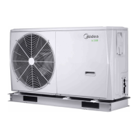
9.1 Opening the unit
Door 1 gives access to the compressor compartment and electrical
parts.
Door 2 gives access to the hydraulic compartment and electrical
parts.
Push the grill to the left until it stops. then pull its right edge, the grill
can now be removed. You can also reverse the procedure. Exercise
caution to avoid a possible hand injury.
Parts inside the unit may be hot.
CAUTION
WARNING
Switch off all power — i.e. unit power supply and backup heater
and domestic hot water tank power supply (if applicable) —
before removing doors 1 and 2.
9.2 Main components
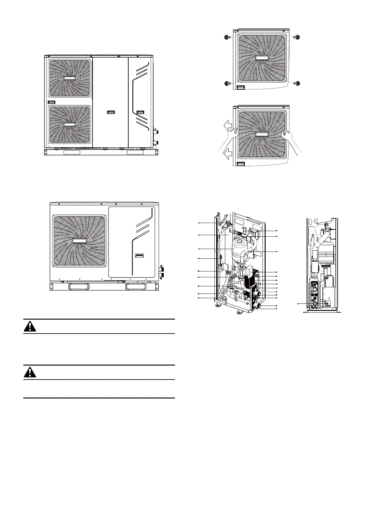
9.2.1 Hydraulic compartment
1.Air purge valve
Remaining air in the water circuit will be automatically removed via
the air purge valve.
2.Backup heater
The backup heater consists of an electrical heating element that
will provide additional heating capacity to the water circuit if the heating
1-phase 10~16kW
3-phase 12~16kW
capacity of the unit is insufficient due to low outdoor temperatures.
It also protects the external water piping from freezing.
3.Expansion vessel (1.32 gallons (5 L))
4.Pressure Sensor
5.Refrigerant gas connection
6.Temperature sensors
Four temperature sensors determine the water and refrigerant
temperature at various points in the water circuit.
6.1-T2B; 6.2-T2; 6.3-T1; 6.4-TW_out; 6.5-TW_in
7.Refrigerant liquid connection
8.Manometer
The manometer provides a water pressure readout of the water
circuit
18
1 2
1
2
3
4
5
6.1
6.5
7
8
9
6.3
10
6.4
11
12
13
14
15.3
15.1
15.2
12.1
14.1
6.2
T1
T2
T2B
TW_in
TW_out
 Loading...