EasyManuals Logo
Home>Midea>Air Conditioner>V8 Series

Midea V8 Series User Manual

Midea V8 Series
130 pages
To Next Page IconTo Next Page
To Previous Page IconTo Previous Page
Page #16 background imageLoading...
Page #16 background image
V8 Mini R410A VRF 50Hz
14
Midea
V8 Mini R410A
Series Engineering Data Book
5.2 Example
The following is a selection example based on total heat load for cooling.
Figure 1-5.1: Room plan
Room A
Room B
Room C
Room D
Step 1: Establish design conditions
Indoor air temperature 25°C DB, 18°C WB; outdoor air temperature 33°C DB.
Determine peak load of each room and system peak load. As shown in Table 1-5.1, the system peak load is 10.5kW.
Table 1-5.1: Required heat load of each room (kW)
Time
Room A
Room B
Room C
Room D
Total
9:00
2.5
1.6
1.6
1.6
7.3
12:00
3.2
2.4
2.4
2.4
10.4
14:00
3.1
2.4
2.4
2.6
10.5
16:00
3.1
2.3
2.3
2.3
10
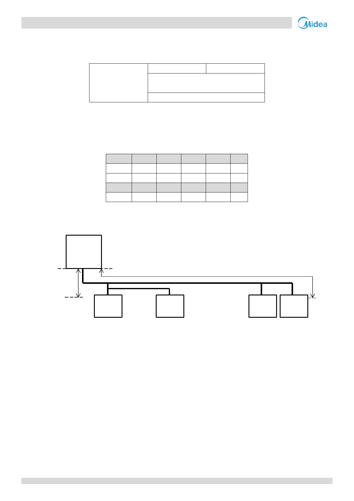
The maximum piping lengths and level differences in this example are as given in Figure 1-5.2.
Figure 1-5.2: System diagram
Indoor unit type for all rooms: Medium Static Pressure Duct (T2).
Step 2: Select indoor units
In this example, a safety factor is not used (i.e. the safety factor is 1).
Select indoor unit models using the medium static pressure duct cooling capacity table. Each indoor unit's corrected
capacity needs to be greater than or equal to the peak load of the relevant room. The selected indoor units are shown
in Table 1-5.3.
Equivalent length of piping 20m
Level
difference
10m
Outdoor
Unit
Indoor
Unit
Indoor
Unit
Indoor
Unit
Indoor
Unit

Other manuals for Midea V8 Series

Questions and Answers:

Question and Answer IconNeed help?

Do you have a question about the Midea V8 Series and is the answer not in the manual?

Midea V8 Series Specifications

General IconGeneral
BrandMidea
ModelV8 Series
CategoryAir Conditioner
LanguageEnglish

Related product manuals