V8 Mini R410A VRF 50Hz
13
Part 1
-
General Information
5 Selection Procedure
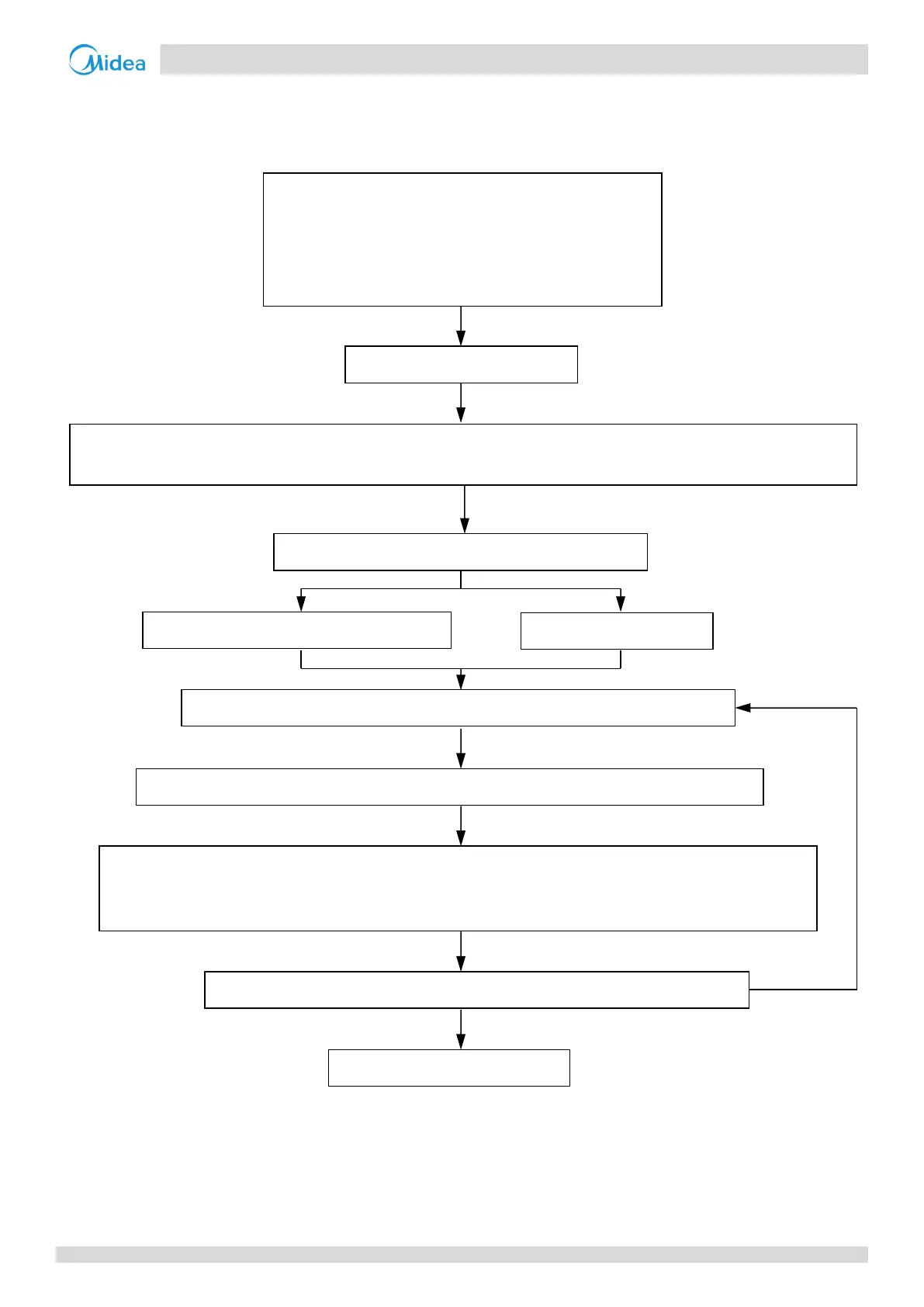
5.1 Procedure
Step 1: Establish design conditions
Step 2: Select indoor units
Step 3: Select outdoor units
Notes:
1. If the indoor design temperature falls between two temperatures listed in the indoor unit's capacity table, calculate the corrected capacity by interpolation.
If the indoor unit selection is to be based on total heat load and sensible heat load, select indoor units which satisfy not only the total heat load
requirements of each room but also the sensible heat load requirements of each room. As with total heat capacity, the sensible heat capacity of indoor
units should be corrected for indoor temperature, interpolating where necessary. For the indoor unit capacity tables, refer to the indoor unit technical
manuals.
Design temperature and humidity (indoor and outdoor)
Required heat load of each room
System peak load
Piping length, level differences
Indoor unit specifications (type and quantity)
Decide indoor unit safety factor
Select indoor unit models ensuring that:
Indoor unit capacity corrected for indoor air temperature WB
1
≥ Required heat load × Indoor unit safety factor
Determine required total heat load on outdoor units
Use the sum of the peak load of each room
Provisionally select outdoor unit capacity based on combination ratio limitations
Confirm that the number of indoor units connected to the outdoor units is within limitation
Correct cooling and heating capacities of the outdoor units for the following items:
Outdoor air temperature / Indoor air temperature WB / Combination ratio / Piping length, level
difference / Piping heat loss / Frost accumulation (for heating capacity only)
Is corrected outdoor unit capacity ≥ Required total heat load on outdoor units?
VRF system selection is complete

 Loading...