V8 Mini R410A VRF 50Hz
83
Part 3 - System Design and Installation
3 Refrigerant Piping Design
3.1 Design Considerations
Refrigerant piping design should take account of the following considerations:
The amount of brazing required should be kept to a minimum.
On the two inside sides of the first indoor branch joint (“A” in Figures 3-3.1 and Figure 3-3.3) the system should, as far
as possible, be equal in terms of number of units, total capacities and total piping lengths.
3.2 Material Specification
Only seamless phosphorus-deoxidized copper piping that complies with all applicable legislation should be used. Temper
grades and minimum thicknesses for different diameters of piping are specified in Table 3-3.1.
Table 3-3.1: Piping temper and thickness
Piping outer
diameter
(mm)
Notes:
1. O: coiled piping;
2. 1/2H: straight piping.
3.3 Permitted Piping Lengths and Level Differences
The piping length and level difference requirements that apply are summarized in Table 3-3.2 and are fully described as
follows (refer to Figure 3-3.1 and Figure 3-3.2):
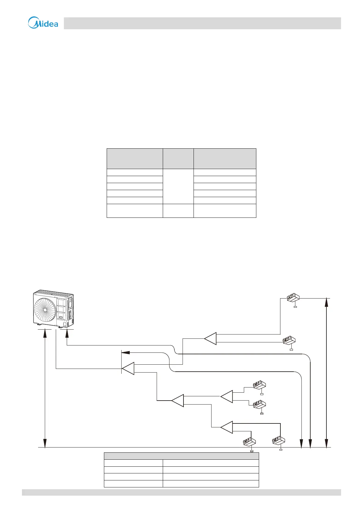
Figure 3-3.1: Permitted refrigerant piping lengths and level differences
Outdoor Unit
a
N1
3N
5N
6
N
2
N
4N
b
c
e
f
d
1L
2L
5L
3
L
4
L
A
B
C
D
E
Maximum level difference between the
outdoor unit and indoor unit is ≤ 50 m
Maximum level difference between Indoor
units is ≤ 15 m
Maximum piping length from the first branch joint
to the farthest indoor unit is ≤ 40 m
Maximum equivalent piping length from the outdoor
unit to the farthest indoor unit is ≤ 120 m
First branch
joint

 Loading...