V8 Mini R410A VRF 50Hz
86
Midea V8 Mini Series Engineering Data Book
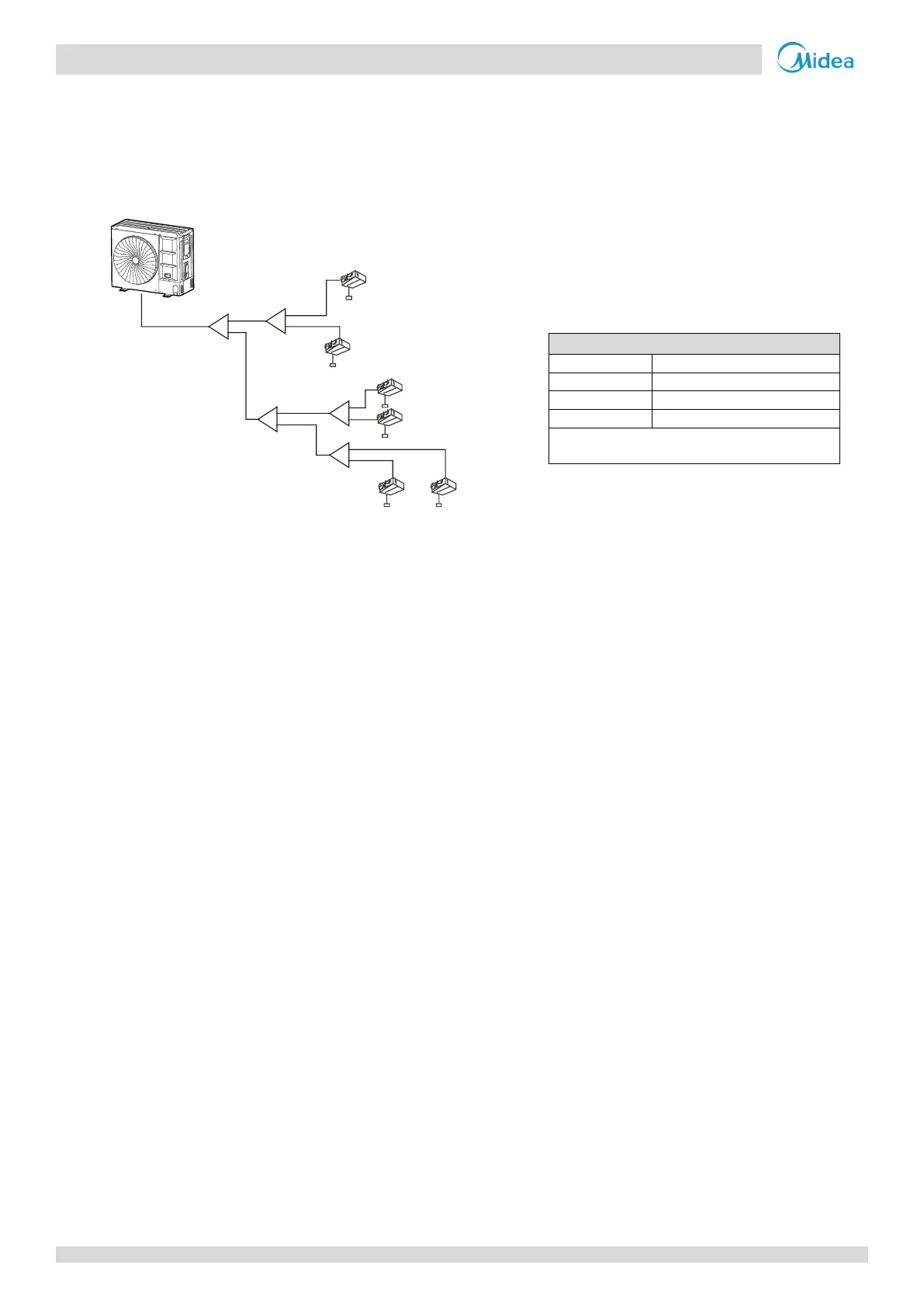
3.5 Refrigerant Piping Selection Example
The example below illustrates the piping selection procedure for a system consisting of an outdoor unit (160 model) and 6
indoor units (2.2 kW×1+2.8 kW×5), as shown in Figure 3-3.4. The system's total equivalent length of all liquid and gas pipes
is less than 90m.
Figure 3-3.4: Refrigerant piping selection example
Step 1: Select indoor auxiliary pipes a to f
The capacity of indoor units N1 to N6 are less than 6.3kW. Refer to Table 3-3.6. Indoor auxiliary pipes a to f are Φ12.7
/ Φ6.35.
Step 2: Select indoor main pipes (L2 to L5) and indoor branch joints B to E
Refer to Table 3-3.5
The indoor units (N1 and N2) downstream of indoor branch B have a total capacity of 2.8*2=5.6kW. Indoor main pipe
L2 is Φ15.9 / Φ9.52. Indoor branch joint B is FQZHN-01D.
The indoor units (N3 and N4) downstream of indoor branch D have a total capacity of 2.8*2=5.6kW.. Indoor main pipe
L4 is Φ15.9 / Φ9.52. Indoor branch joint D is FQZHN-01D.
The indoor units (N5 and N6) downstream of indoor branch E have a total capacity of 2.8+2.2=5.0kW.. Indoor main pipe
L5 is Φ15.9 / Φ9.52. Indoor branch joint E is FQZHN-01D.
The indoor units (N3 to N6) downstream of indoor branch C have a total capacity of 5.6+5.0=10.6kW. Indoor main pipe
L3 is Φ15.9 / Φ9.52.Indoor branch joint C is FQZHN-01D.
Step 3: Select main pipe (L1) and indoor branch joint A
The indoor units (N1 to N6) downstream of indoor branch joint A have a total capacity of 5.6+10.6=16.2kW. The system's
total equivalent length of all liquid and gas pipes is less than 90m. The outdoor units model is 160. Main pipe L1 is
Φ19.1/Φ9.52. First Indoor branch A is FQZHN-01D. Refer to Table 3-3.6.
Outdoor Unit
N1
(28)
N3
(28)
N5
(28)
N6
(22)
N2
(28)
N4
(28)
A
B
D
E
C
a
b
c
e
f
d
L1
L2
L5
L3
L4
Figures in parentheses indicate indoor unit
capacity indexes.

 Loading...