1.
2.
3.
4.
5.
6.
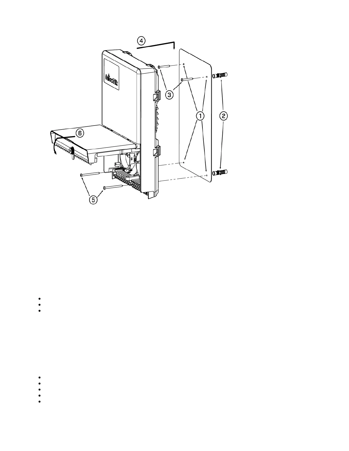
Use included a template to mark spots for drilling holes. Align accordingly, it will depend on how the device will be mounted finally.
Insert dowels if needed, depending on wall structure and material.
Insert screws and screw them by leaving approximately 1 cm out.
Attach the unit to the position.
Use screw holes under the bottom cover and tighten them to secure them in place. Extend your Ethernet cables through the openings and
connect to Ethernet ports.
Close bottom latch.
Carefully check the wall for electric cables before drilling mounting holes.
Buttons and jumpers
The RouterBOOT reset button has the following functions. Press the button and apply the power, then:
Release the button when the green LED starts flashing, to reset RouterOS configuration to defaults.
Release the button when the LED turns solid green to clear all configurations and bridge all interfaces.
Release the button after LED is no longer lit (~20 seconds) to cause a device to look for Netinstall servers (required for reinstalling RouterOS over
the network).
Regardless of the above option used, the system will load the backup RouterBOOT loader if the button is pressed before power is applied to the device.
Useful for RouterBOOT debugging and recovery.
Accessories
The package includes the following accessories that come with the device:
EU Switching Power Supply 48V, 0.95A;
Gigabit POE injector;
Hose Clamp SUS304;
OED-drill-template, paper brochure;
K-66 fastening set.
 Loading...