MSIN0201BE/2002372V
ÈHYDRO-CUSHION
®
SERVICE CONNECTIONS
ÊGeneral
These service connections are required:
1. Piped inlets and outlets (cold water, hot water, “third” water,
reuse water, flushing supply water, Spray down and/or cool-
down water, steam, central liquid supply, peristaltic pump inlets,
compressed air inlet, vent, reuse and/or drain).
2. Electric power connections (for additional information see “EXTERNAL FUSE AND WIRE SIZES FOR
MILNOR
®
MACHINES” - MAEFUSE1AE).
ÊRequirements for Piped Connections
Inlet pressures must be within the minimum/maximum range specified. Pressures outside of the specified
range may cause the machine to operate inefficiently or malfunction, and may damage machine components.
MACHINE DAMAGE—Valve bodies will be ruined if twisted and distorted.
☞ Hold the connection side of the valve with a wrench when connecting plumb-
ing.
MACHINE DAMAGE—Piping will be damaged if struck by tilting machine.
☞ Route piping to tilting machines carefully.
Machine Damage Hazards—Pumped chemical systems, if not properly in-
stalled, can cause corrosion damage.
☞ See the reference manual for precautions and additional information before
making any chemical connections.
ËPiped Inlet/Outlet Specifications
—The piped inlet and outlet requirements are as follows (see dimen-
sional drawings for the size and location of connection points):
ÏPiped Inlets
Description of Connection Source Requirements Piping Specifications
Cold water inlet See dimensional drawing
for size.
30 - 65 PSI
(2.10 - 4.57 kilogram/centimeter)
Pipe material per plumbing code
(see “Piped Inlet Precautions,”
in this section)
Hot water inlet
“Third” water inlet
Reuse water inlet
Steam inlet See dimensional drawing for size.
30 - 115 PSI
(2.10 - 4.57 kilogram/centimeter)
Pipe material per plumbing code
(see “Steam Precautions”,
in this section
Flushing water for supply injector
(Divided cylinder, 52", and 72"
open pocket non-tilt machines only)
See dimensional drawing for size.
30 - 65 PSI
(2.10 - 4.57 kilograms)
Pipe material per plumbing code
(see “Flushing Water Connections,”
in this section)
Peristaltic pump inlets 1/2" NPT
Flexible tubing as specified
by chemical supplier
(see “Peristaltic Pump
Connections,” in this section)
Central liquid supply 1/2" and 3/8" NPT Flexible tubing as specified
by chemical supplier
Compressed air inlet See dimensional drawing for size.
85 - 115 PSI
(5.97 - 8.08 kilogram/centimeter)
Pipe material per plumbing code
ËOutlet Specifications
—The outlet requirement is as follows. See dimensional drawings for connection sizes
and locations.
ÏOutlets
Description of Connection Destination Requirements
or Description
Piping Specifications
Drain to reuse
(if so equipped)
or
Drain to sewer
Provide a centrally located open
trench, with a minimum slope of
1/8" per foot (10 mm per meter)
(See dimensional drawing)
Do not connect dump valves to
drain. Attach short pieces of hose to
dump valves to control splashing.
Do not immerse ends of hoses.
(see “Drains” in this section)
Vent See dimensional drawing Flexible tubing supplied by others
(see “Vents” in this section)
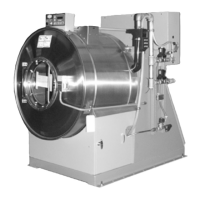
IT IS NORMAL FOR THE VEGETABLE FIGER
GASKET ON THIS SHELLFRONT TO LEAK
SLIGHTLY WHEN THE MACHINE IS FIRST
COMMISSIONED. IT SHOULD STOP LEAKING
AFTER THE FIRST FEW LOADS ARE PROCESSED.
ÎFIGURE 1
(MSIN0201BE)
ÎAll Machines
34
 Loading...