Trio™ Service Manual 0070-10-0591-01 1 - 7
Theory of Operation Hardware Overview
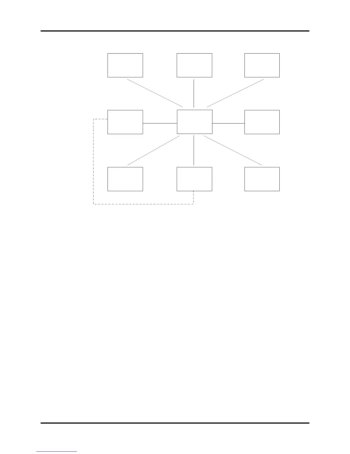
FIGURE 1-5 Block Diagram of Trio CPU board
1.2.3.2 Detailed Description
3.3 V low-voltage power supply component is used. The external power is 5 V, which is
converted by the DC/DC converter into 3.3 V and 2.5 V, the latter voltage being especially
used for FPGA. The main control board is connected to external devices via corresponding
interfaces and input: the power supply connected to the interface board, the 9-way serial
port, TFT interface, analog VGA interface, network interface, analog output and a spare
serial port, etc. The BDM interface, on the board, is reserved for the purpose of software
testing and downloads.
CPU
Uses Coldfire 5206e. Clock rate is 54 MHz, working voltage is 3.3 V.
FLASH
Uses two parallel-connected 512K x 16 or 1M x 16* FLASH memories. The output terminal
PP1 of CPU is used to realize write-protection of FLASH. It is effective in low-level state.
*Applies to P/N 0671-00-0056.
DRAM
The Trio CPU main control board uses two parallel-connected 1M x 16 DRAM, which
construct 4M address space.
alarm/spare
battery
DRAM
RTC/E PROM
2
Interrupt
management
circuit
I/O serial
interface
CPU
FPGA
Display
driving
circuit
 Loading...