( )
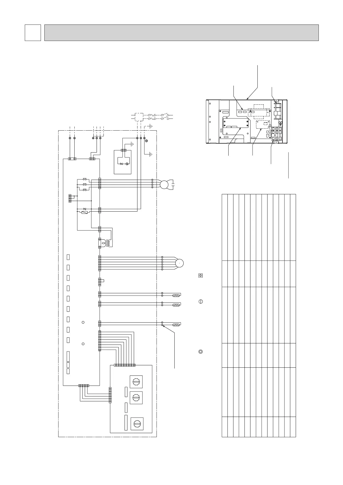
PARTS LOCATION
INSIDE SECTION OF CONTROL BOX
AC250V
6.3A T
CN22CN27CN25CN24CN23
531
FAN2
SW14
(Connection No.)
SW12
(2nd digit)
SW11
(1st digit)
F
LED2
LED1
CN32 CN52 CN51 CN41
SW7
1
2
1
3
CN3A
CN31
12
2
1
I.B.
CN2M
FAN3
CND
CNT
CN60
CN21CN20
CN81
1
2
3
45
6
1
1
1
1
3
5
2
3
2
2
2
3
31
3
4
4
1
56
L1
L2
LEV
MF
TH22
SW3
SW2
SW1
M1
S(SHIELD)
M2
1
3
CN3T
A.B.
6
5
4
3
2
1
7
8
CN29
1
2
TH23
8
7
1234
1
2
3
4
CN42
SW4
TH21
7
1
3
1
4
XO4XO5XO6
ZNR
2
T
1
3
1
2
1
3
1
2
654321
654321
ZNR1
3
1
CN1
DSA1
S.B.
CN82
CN62
SW5
56
G
TB15 (TRANSMISSION TERMINAL BED)
8
7
5
6
4
3
2
0
9
1
9
0
1
2
3
4
5
6
7
8
F
E
D
C
B
A
9
0
8
7
6
5
4
3
2
1
TB2
TB5 (TRANSMISSION TERMINAL BED)
C
Varistor
ZNR,ZNR1
Connector
CN27
Connector
CN25
Connector
CN24
Connector
CN23
Connector
CN22
NAME SYMBOL
NAME SYMBOL
NOTE;1.The wirings to TB2,TB5,TB15 shown in chained line are field work.
2.Mark indicates terminal bed, connector, board insertion
connector or fastening connector of control board.
Connector (Remote indication)
CN52
Connector (Centrally control)
CN51
Connector (HA terminal-A)
CN41
Connector (Centrally control)
CN32
Power supply (Remote controller)
LED2
Power supply (I.B.)
LED1
SW7(A.B.)
Transmission terminal bed
TB15
MF
C
I.B.
A.B.
F
T
LEV
TH21
TH22
SW11(A.B.)
SW12(A.B.)
SW1(A.B.)
SW2(I.B.)
SW3(I.B.)
TH23
SW14(A.B.)
SW4(I.B.)
SYMBOL EXPLANATION
SYMBOL NAME
Fuse AC250V 6.3A T
Transformer
Electronic linear expan. valve
Fan motor
Capacitor (for MF)
Indoor controller board
Address board
Thermistor (inlet temp.detection)
Switch (1st digit address set)
TB2
Power source terminal bed
TB5
Transmission terminal bed
S.B.
Surge absorber board
X04~06
SW5(A.B.)
A.B.
I.B.
S.B.
TB5,TB15
TB2
CONTROL BOX
Switch(for model selection)
TO MA REMOTE CONTROLLER
Switch(for mode selection)
Switch(for capacity code)
Switch(for model selection)
Switch(for mode selection)
Thermistor (piping temp.detection/liquid)
Thermistor (piping temp.detection/gas)
Switch (2nd digit address set)
Switch (connection No.set)
Aux.relay
Switch(for voltage selection)
TO OUTDOOR UNIT
BC CONTROLLER
REMOTE CONTROLLER
TO NEXT INDOOR UNIT
PULL BOX
FUSE(15A)
BREAKER(15A)
POWER SUPPLY
~208/230V 60Hz
MODEL 06/08 ONLY
(Green)(Red)(Green) (Yellow) (White)
(Yellow)
(Yellow)
(White)
(White)
(Blue)
(Blue)
(White)
(Red)
(White)
(White) (Red)
(Black)
(White)
(Red) (White)
(Red)
(Red)
(White)(White)(Green)(White)
(White)
(Black) (White)
(White)
(Red)
 Loading...