© 2016 Mitsubishi Electric US, Inc.
Due to continuing improvement, above specication may be subject to change without notice.
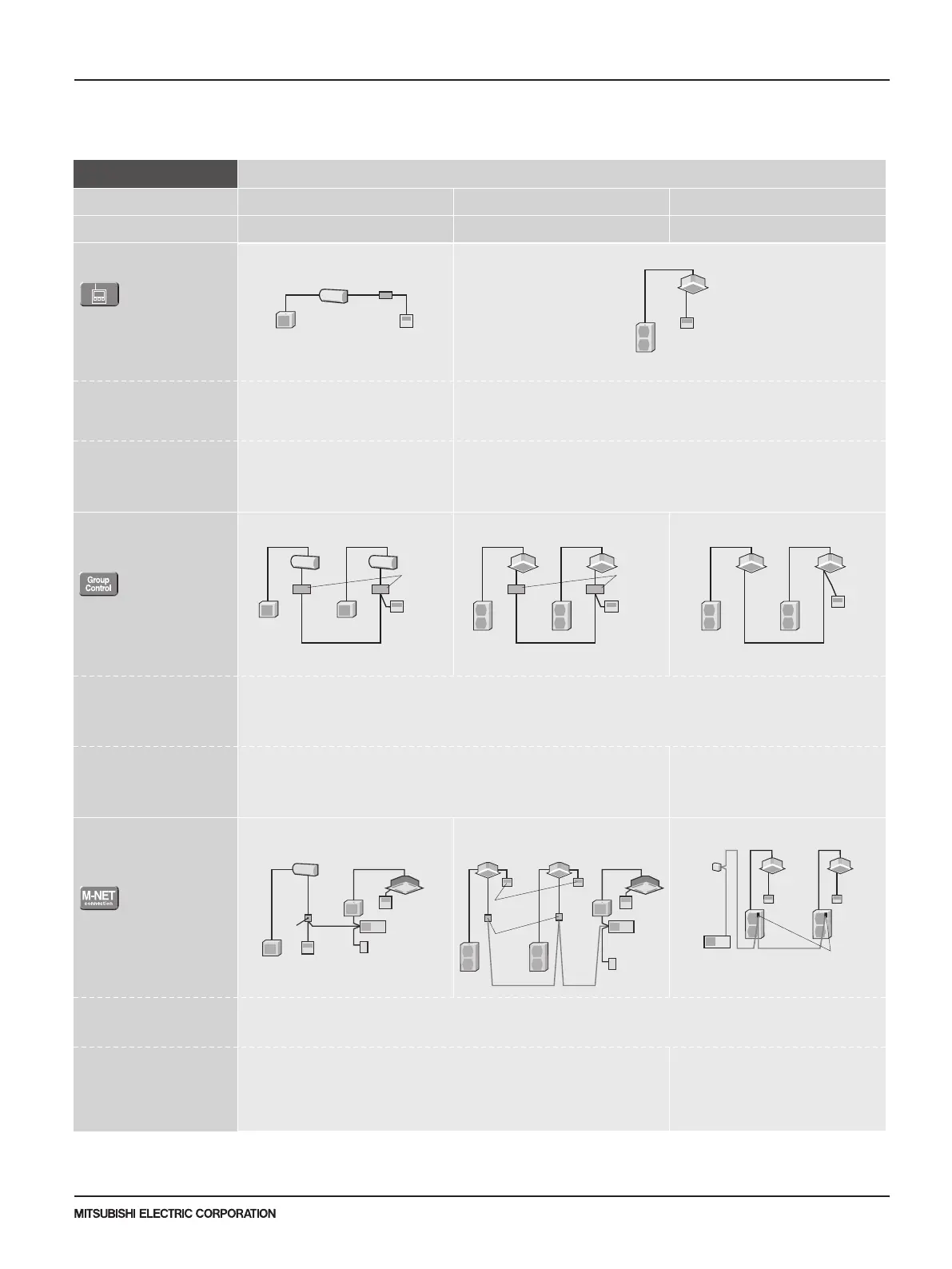
■OTHERS
2-remote Controller
Control
With two remote controllers, control
can be performed locally and
remotely from two locations.
Operation Control by
Level Signal
Air conditioner can be started/
stopped remotely. In addition,
On/Off operation by local remote
controller can be prohibited/permitted.
Operation Control by
Pulse Signal
Remote Display of
Operating Status
Operating status can be
displayed at a remote location.
PAC-YT53CRAU
(Example of 1 : 1 system)
(Example of 1 : 1 system)
Relay box (to be purchased) locally)
Relay box (to be purchased) locally)
Adapter for
remote
On/Off
Adapter for
remote
On/Off
PAR-FL32MA
PAR-FL32MA
(Example of 1 : 1 system x 2)
Relay box (to be purchased locally)
(Example of 1 : 1 system x 2)
* Set "Main" and "Sub"
remote controllers.
* When using wired and
wireless remote controllers
PAR-FL32MA
(Example of Simultaneous Twin)
(Example of Simultaneous Twin)
• Wired Remote Controller
PAC-YT53CRAU
• Wireless Remote Controller
PAR-FL32MA
• Wireless Remote Controller Kit for PCA
PAR-SL93B-E
• Adapter for remote On/Off
PAC-SE55RA-E
• Relay box (to be purchased locally)
• Remote control panel (to be purchased
locally)
A
B
C
D
Details
Major Optional Parts Required
System Examples
Wired remote controller Wireless remote controller
Remote
display
panel
Remote
display
panel
PAC-YT53CRAU
Remote
control
panel
Remote
control
panelWired remote
controller
• Up to two remote controllers can be
connected to one group.
• Both wired and wireless remote controllers
can be used in combination.
• Operation other than On/Off (e.g., adjust-
ment of temperature, fan speed, and airflow)
can be performed even when remote
controller operation is prohibited.
• Timer control is possible with an external
timer.
Connector
cable for
remote
display
Connector
cable for
remote
display
PAR-FL32MA
(Example of 1 : 1 system x 2)
Relay box (to be purchased locally)
(Example of 1 : 1 system x 2)
• Connector cable for remote display
PAC-SA88HA-E / PAC-725AD
(10 pcs. x PAC-SA88HA-E)
• Relay box (to be purchased locally)
• Remote control panel (to be purchased
locally)
Remote
control
panel
Remote
control
panelWired remote
controller
• The pulse signal can be turned On/Off.
• Operation/emergency signal can be
received at a remote location.
• Operation/emergency signal can be
received at a remote location (when
channeled through the PAC-SF40RM-E
no-voltage signal, when channeled through
the PAC-SA88HA-E DC 12V signal).
• Remote display panel (to be purchased
locally)
• Connector cable for remote display
PAC-SA88HA-E / PAC-725AD
(10 pcs. x PAC-SA88HA-E)
• Relay box (to be purchased locally)
• Remote operation adapter
PAC-SF40RM-E
*Unable to use with wireless remote controller
Remote operation adapter/
Connector cable for remote display +
Relay box
Remote operation adapter/
Connector cable for remote display +
Relay box
For P Series and S Series Indoor Units
For M Series Indoor Units (New A-control Models Only)
1
2
Remote On/Off
Operation
Remote Display of
Operation Status
Control Details Major Optional Parts RequiredSystem Examples Connection Details
• MAC-333IF-E
(Interface)
• Parts for circuit such as relay
box, lead wire, etc. (to be
purchased locally)
• MAC-333IF-E
(Interface)
• Parts for circuit to be
purchased locally (DC power
source needed)
• External power source (12V DC)
is required when using
MAC-333IF-E.
Connect the interface to the air
conditioner. Then connect the
locally purchased remote controller
to the terminal in the interface.
Connect the interface to the air
conditioner. Then connect the
locally purchased remote controller
to the terminal in the interface.
On/Off operation is possible from
a remote location.
The operation status
(On/Off) or error signals can be
monitored from a remote location.
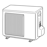
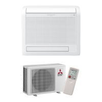
Outdoor unit
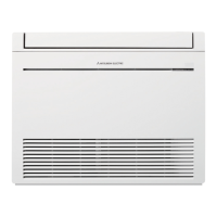
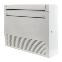
Indoor unit
MAC-333IF-E
Remote control section
(to be purchased locally)
Switch
• Air conditioner can be started/
stopped remotely.
( 1 and 2 can be used in
combination)
• The On/Off status of air
conditioners can be confirmed
remotely.
( 1 and 2 can be used in
combination)
For M Series Indoor Units (FH series Only)
1
Interface which outputs
the ON/OFF signals
from the air conditioner
to the back-up heater.
(This and MAC333IF-E can be
used in combination)
Control Details Major Optional Parts RequiredSystem Examples Connection Details
• MAC-1702/1710RA-U
(Connector Cable)
• Parts for circuit such as relay
box, lead wire, etc.(to be
purchased locally)
Connect the connector cable to the
air conditioner. Then connect the
locally purchased buck-up heater
to the electrical wire of connector
cable.
It can control the On/Off operation
of buck-up heater.
• Group of air conditioners can be controlled by MELANS system controller (M-NET).
• One remote controller can control plural air conditioners with the same settings simultaneously.
• One remote controller can control up to 16 refrigerant systems. (When connected to a MXZ unit, MAC-333IF-E is counted as one system.)
• Up to two remote controller can be connected.
1. CONTROLS
1-1. System Control
 Loading...