EN-7
EN
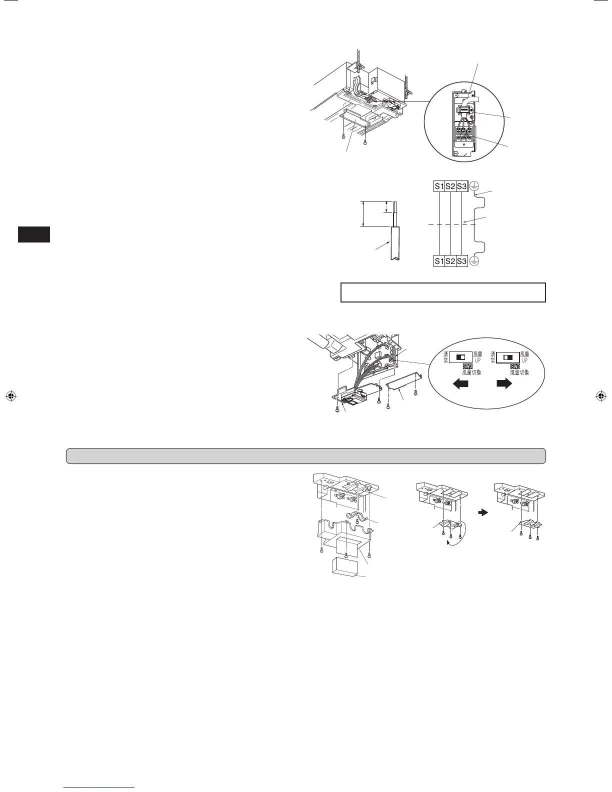
Indoor terminal block
Indoor/outdoor unit
connecting wire
D
Outdoor terminal block
Earth wire
(green/yellow)
• Make earth wire a little longer than others. (More than 55 mm)
• For future servicing, give extra length to the connecting wires.
2-4. CONNECTING WIRES FOR INDOOR UNIT
1) Remove electrical cover (1).
2) Remove cord clamp.
3) Pass indoor/outdoor unit connecting wire
D
process the end of the wire.
4) Loosen terminal screw, and connect rst the earth wire, then indoor/outdoor
unit connecting wire
D
to the terminal block. Be careful not to make mis-
wiring. Fix the wire to the terminal block securely so that no part of its core is
appeared, and no external force is conveyed to the connecting section of the
terminal block.
5) Firmly tighten the terminal screws to prevent them from loosening. After
tightening, pull the wires lightly to conrm that they do not move.
6) Secure indoor/outdoor unit connecting wire
D
and the earth wire with the
cord clamp. Never fail to hook the left claw of the cord clamp. Attach the cord
clamp securely.
Lead wire
3-1. PIPING WORK
1) Remove the pipe cover, hose band, pipe band, and spacer (cushion) of the
indoor unit. Dispose of the spacer (cushion), as it will not be needed.
2) When using pipe with super insulating material (about ø48 mm liquid pipe,
ø51 mm gas pipe) for indoor connecting pipe, remove plate and turn it over
so that the concave part faces upward.
When the ceiling is above 2.4 m and 2.7 m or below
Move the slide switch (SW3) to the right to increase airow volume.
* When the ceiling is above 2.7 m, airow volume may be insufcient even with
the slide switch (SW3) set to “increase airow”.
1) Make sure that the breaker for air conditioner is turned OFF.
2) Remove electrical cover (1) and (2) of the indoor unit.
3) Slide out the electronic control P.C. board, and switch up the slide switch (SW).
4) Put the electronic control P.C. board back to the original position, and install
electrical cover (1) and (2).
Note:
• Perform static elimination before setting.
• Default setting is Normal.
Electrical cover (1)
Electrical cover (2)
Electronic
control P.C.
board
Plate
Pipe band
Plate
(turn over)
Plate
35 mm
15 mm
Pipe cover
Electrical cover (1)
Slide switch SW3
Normal Increase airow
volume
Spacer (cushion)
3. FLARING WORK AND PIPE CONNECTION
Indoor/outdoor unit
connecting wire
D
Cord clamp
Terminal block
[When using pipe with super insulating material]
RG79Y972H01_01En.indd 7 2018/02/27 10:52:18
 Loading...