1.
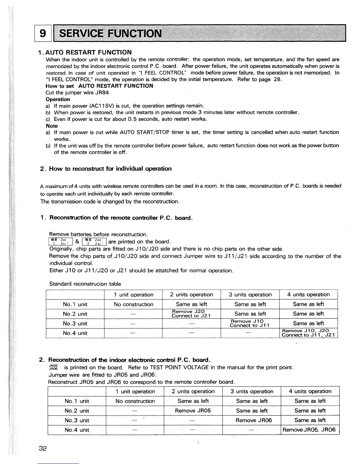
AUTO RESTART FUNCTION
When the indoor unit is controlled by the remote controller; the operation mode, set temperature, and the fan speed are
memorized by the indoor electronic control P.C. board. After power failure, the unit operates automatically when power is
restored. In case of unit operated in
'I
FEEL CONTROL"
mode before power failure, the operation is not memorized. In
'I
FEEL CONTROL" mode, the operation is decided
by
the initial temperature. Refer to page 28.
How to set AUTO RESTART FUNCTION
Cut the jumper wire JR84
Operation
a) If main power
(ACI 15V) is cut, the operation settings remain.
b)
When power is restored, the unit restarts in previous mode
3
minutes later without remote controller.
c) Even if power is cut for about 0.5 seconds, auto restart works.
Note
a) If main power is cut while AUTO START/STOP timer is set, the timer setting is cancelled when auto restart function
works.
b) If the unit was off by the remote controller before power failure, auto restart function does not work as the power button
of the remote controller is off.
[q
2.
How to reconstruct for individual operation
SERVICE FUNCTION
A
maximum of
4
units with wireless remote controllers can
be
used in a room. In this case, reconstruction of
P.C.
boards is needed
to operate each unit individually by each remote controller.
The transmission code is changed by the reconstruction.
1
.
Reconstruction of the remote controller
P.
C.
board.
Remove batteries before reconstruction.
/-
&
I&
are printed on the board.
Originally, chip parts are fitted on J10/J20 side and there is no chip parts on the other side.
Remove the chip parts of
J
10/J20 side and connect Jumper wire to J11 /J21 side according to the number of the
individual control.
Either J 10 or J 1
1
/J20 or J2 1 should be attatched for normal operation.
Standard reconstrucion table
1
/
1 unit operation
1
2 units operation
1
3
units operation
1
4
units operation
1
/
No.
1
unit No construction
1
Same as left
I
Same as left
I
Same as left
I
Reconstruction of the indoor electronic control
P.
C
.
board.
JR05
JR06
is printed on the board. Refer to TEST POINT VOLTAGE in the manual for the print point.
Jumper wire are fitted to JR05 and JR06.
Reconstruct JR05 and JR06 to corespond to the remote controller board.
L
No.2 unit
No.3 unit
No.4 unit
I
I
1 unit operation
1
2 units operation
1
3
units operation
1
4
units operation
/
-
-
-
No.
1
unit
No.2 unit
/
No.4unit
1
-
I
-
I
-
I
Remove JR05, JR06
I
Same as left
Remove
J
1
0
Connect
to
J
1 1
-
Connect
to
~2
1
Remove
J20
-
-
No.3 unit
Same as left
Same as left
Remove
J10, J20
Connect
to
J
1
1
,
J2
1
No construction
-
J
-
Same as left
Remove JR05
-
Same as left
Same as left
Same as left
Same as left
Remove JR06
Same as left
 Loading...