2. Installation location
3. Installing the indoor unit
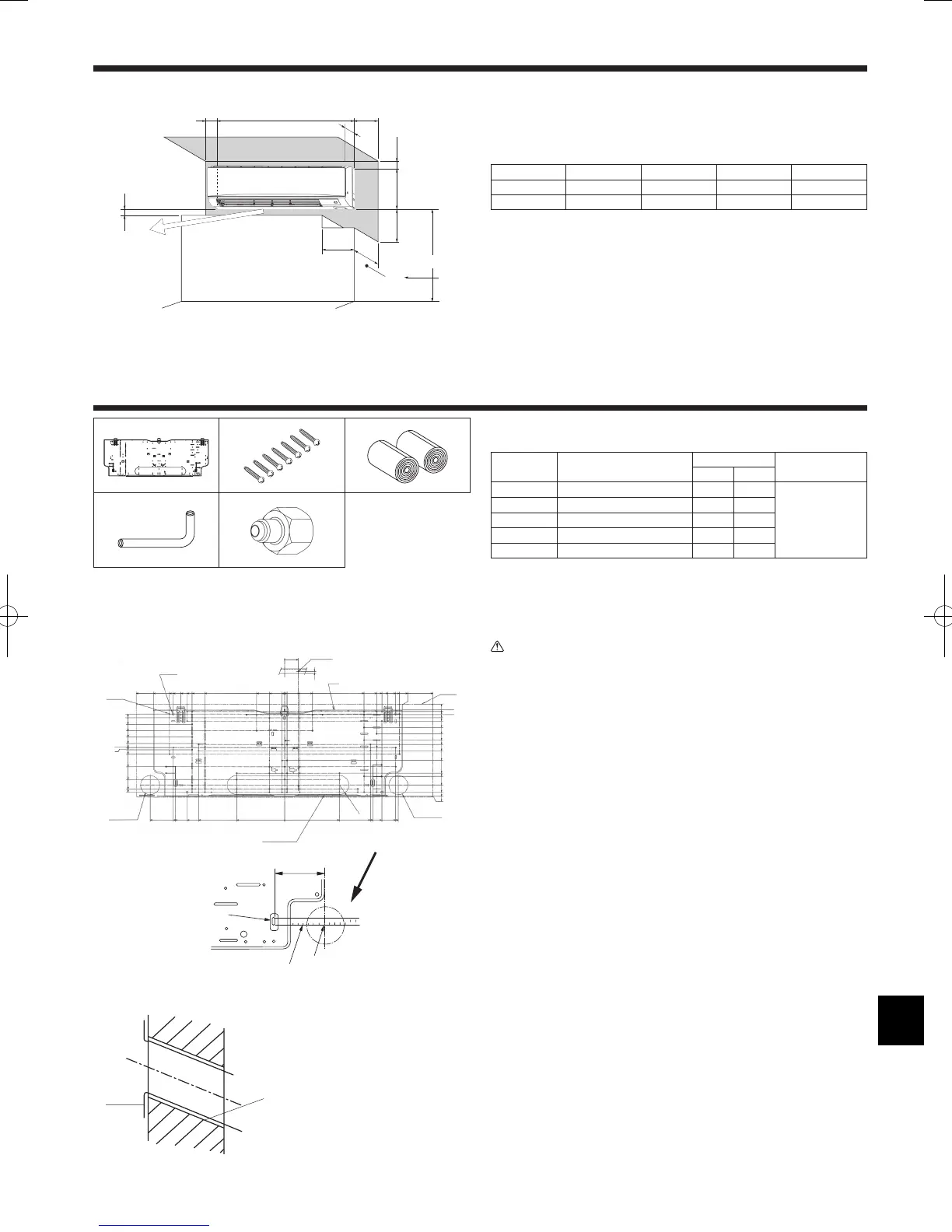
3.1. Check the indoor unit accessories (Fig. 3-1)
The indoor unit should be supplied with the following accessories.
PART NUMBER
ACCESSORY
QUANTITY
LOCATION OF SETTING
P24 P30
1
Mount board 1 1
Fix at the back of the unit
2
Tapping screw 4 × 25
7 7
3
Felt tape 2 2
4
L-shaped connection pipe 1 1
5
Charge nut 1 1
3.2. Installing the wall mounting fixture
3.2.1. Setting the wall mounting fixture and piping positions
► Using the wall mounting fixture, determine the unit’s installation position
and the locations of the piping holes to be drilled.
Warning:
Before drilling a hole in the wall, you must consult the building contractor.
PKFY-P·NKMU-E (Fig. 3-2)
AMount board 1
BIndoor unit
CBottom left rear pipe hole (ø75-ø80 mm, 2-61/64~3-5/32 inch)
DBottom right rear pipe hole (ø75-ø80 mm, 2-61/64~3-5/32 inch)
EKnockout hole for left rear hole
FBolt hole (4-ø9 mm, 23/64 inch hole)
GCenter measurement hole (ø2.5 mm, 3/32 inch hole)
HTapping hole (75-ø5.1 mm, 13/64 inch hole)
IHole centre
JAlign the scale with the line.
KInsert scale.
3.2.2. Drilling the piping hole (Fig. 3-3)
► Use a core drill to make a hole of 75-80 mm, 2-61/64~3-5/32 inch diameter
in the wall in the piping direction, at the position shown in the diagram to
the left.
► The hole should incline so that the outside opening is lower than the
inside opening.
► Insert a sleeve (with a 75 mm, 2-61/64 inch diameter and purchased
locally) through the hole.
Note:
The purpose of the hole’s inclination is to promote drain flow.
Fig. 2-1
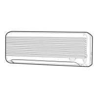
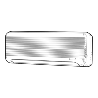
2.1. Outline dimensions (Indoor unit) (Fig. 2-1)
Select a proper position allowing the following clearances for installation and
maintenance.
PKFY-P·NKMU-E
(mm, inch)
A B C D E
Min. 100.5 Min. 52.3 Min. 48 Min. 250 Min. 220
Min. 3-31/32 Min. 2-1/16 Min. 1-7/8 Min. 9-27/32 Min. 8-21/32
FAir outlet: Do not place an obstacle within 1500 mm, 59-1/16 inch of the air outlet.
GFloor surface
HFurnishing
IWhen the projection dimension of a curtain rail or the like from the wall exceeds 60 mm,
2-23/64 inch extra distance should be taken because the fan air current may create a short
cycle.
J1800 mm, 70-7/8 inch or greater from the floor surface (for high location mounting)
K108 mm, 4-1/4 inch or greater with left or rear left piping
LMinimum 7 mm, 9/32 inch
Fig. 3-1
PKFY-P·NKMU-E
Fig. 3-2
 Loading...