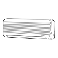
Fig. 4-1
4.1. Connecting pipes (Fig. 4-1)
• When commercially available copper pipes are used, wrap liquid and gas pipes
with commercially available insulation materials (heat-resistant to 100 °C, 212 °F
or more, thickness of 12 mm, 1/2 inch or more).
• The indoor parts of the drain pipe should be wrapped with polyethylene foam
insulation materials (specific gravity of 0.03, thickness of 9 mm, 23/64 inch or
more).
• Apply thin layer of refrigerant oil to pipe and joint seating surface before
tightening flare nut.
• Use two wrenches to tighten piping connections.
• Use refrigerant piping insulation provided to insulate indoor unit connections.
Insulate carefully.
A Flare cutting dimensions
Copper pipe O.D.
(mm, inch)
Flare dimensions
øA dimensions (mm, inch)
ø9.52, 3/8” 12.8 - 13.2, 1/2 - 33/64
ø15.88, 5/8” 19.3 - 19.7, 49/64 - 25/32
B Refrigerant pipe sizes & Flare nut tightening torque
R22 R410A
Flare nut O.D.
Liquid pipe Gas pipe Liquid pipe Gas pipe
Pipe size O.D.
(mm, inch)
Tightening
torque.
(N·m, ft·lbs)
Pipe size O.D.
(mm, inch)
Tightening
torque.
(N·m, ft·lbs)
Pipe size O.D.
(mm, inch)
Tightening
torque.
(N·m, ft·lbs)
Pipe size O.D.
(mm, inch)
Tightening
torque.
(N·m, ft·lbs)
Liquid
pipe
(mm,
inch)
Gas
pipe
(mm,
inch)
P24
P30
ODø9.52
3/8”
34 - 42
25 - 30
ODø15.88
5/8”
68 - 82
49 - 59
ODø9.52
3/8”
34 - 42
25 - 30
ODø15.88
5/8”
68 - 82
49 - 59
22
7/8
29
1-9/64
C Do not apply refrigerating machine oil to the screw portions.
(This will make the flare nuts more apt to loosen.)
DBe certain to use the flare nuts that are attached to the main unit.
(Use of commercially-available products may result in cracking.)
E Apply refrigerating machine oil over the entire flare seat surface.
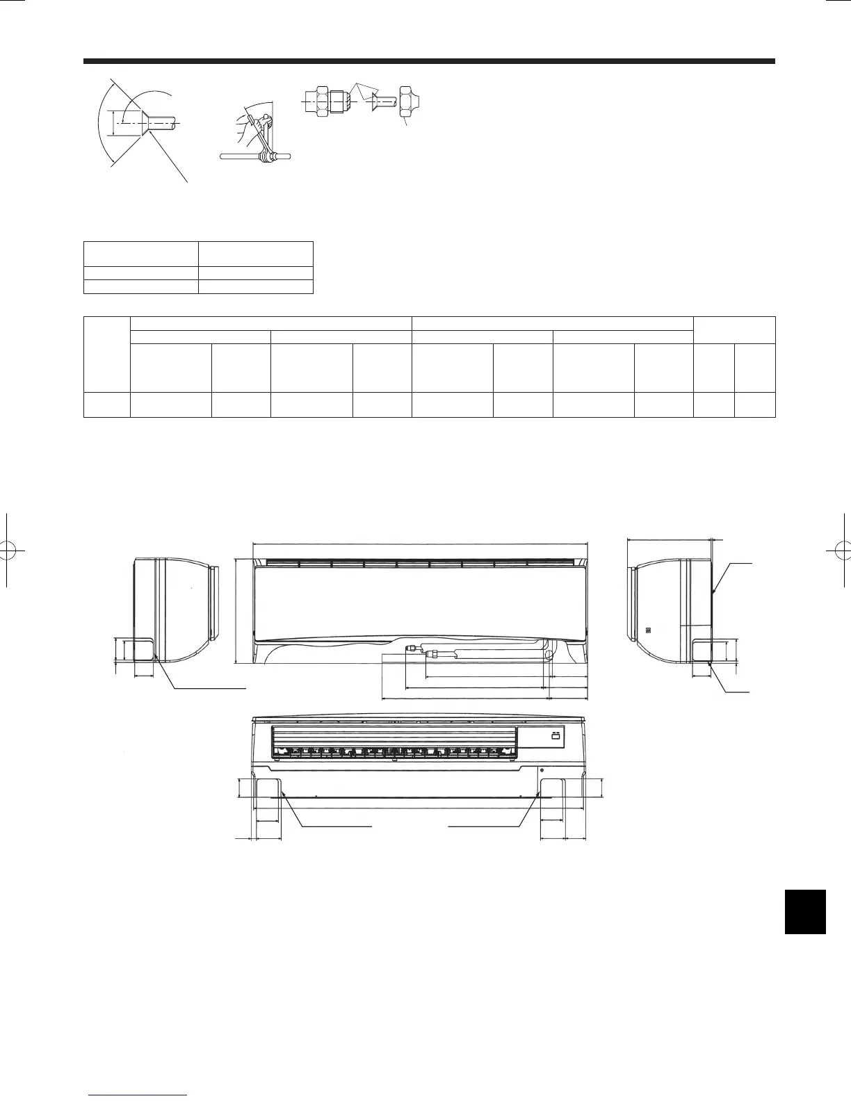
Fig. 4-2
PKFY-P·NKMU-E
4.2. Positioning refrigerant and drain piping (Fig. 4-2)
PKFY-P·NKMU-E
AGas pipe * Indicates the condition with accessories mounted.
BLiquid pipe
CDrain hose
DLeft-side piping knockout hole
ERight-side piping knockout hole
FLower piping knockout hole
G Mount board 1
 Loading...