-
17
-
'20 • KX-T-347
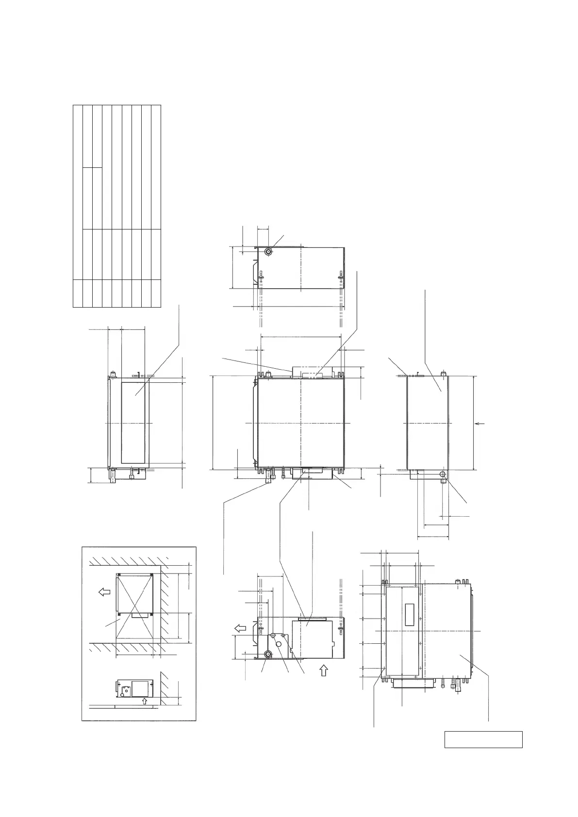
(b) Bottom suction type
F
555
100
100
100
500
1150
Space for installation and service
Unit:mm
Transparent soft tube
Control box(Original position)
145.6
30.8
66
95.3
157
(Accessory)
(Installed on site)
Plate for control box
(Original position)
(To be able to be
located on the
reverse side)
(After bottom plate B is replaced to back side)
Air
outlet
Air inlet
1
C
A
B
Bottom plate A
G
Air inlet
150
54
18.2
54
3030
160
537.6
198.7
29.6
150 150
12-
φ
4
27.5
91
27.5
494.2
83.3
145
(Duct dimension)
(Duct dimension)
Supply air duct
(Suspension bolts pitch)
Plate for control box
(Option position)
38.2
68
21.8
488
65.2
62.1
21
575.2
D
( )
(Control box option position
on the reverse side)
D
( )
68
( )
(Suspension bolts pitch)
530.8
255.8
30.8
66
24.2
2
C
(Back side)
G
D
E
188.5
148.5
574
37.6
Bottom plate B
is located on the Back side
from original position
Notes
(1)The model name label is attached on the fan cose
inside the air return grille.
(2)Prepare the connecting socket (VP20) on site.
(As for drain piping, it is possible to choose C
1
or C
2
)
(3)When control box is located on the reverse side, Installation
space should be modified new location.
×
Inspection hole
Gas piping
Liquid piping
Drain piping
Hole for wiring
Suspension bolts
Symbol
Content
φ6.35(1/4")(Flare)
φ30
Model
22,28
36
φ12.7(1/2")(Flare)
φ9.52(3/8")(Flare)
Drain piping
VP20(I.D.20,O.D.26)Note(2)
To be used instead of "C
1
"
A
B
C
1
D
E
F
C
2
(555 × 1150) Note(3)
(M10)
PJC001Z292
 Loading...