-
21
-
'20 • KX-T-347
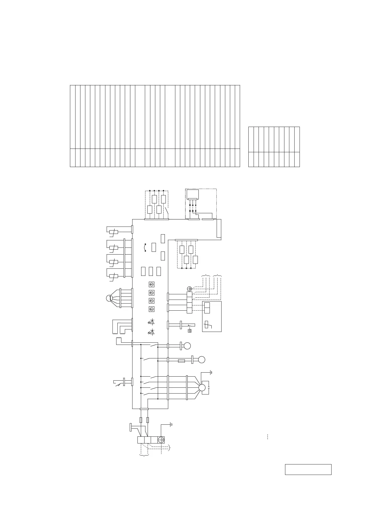
4. ELECTRICAL WIRING
(1) Ceiling cassette-1 way compact type (FDTQ)
(a) Direct blow type
All models
Color marks
Mark
BK
BL
BR
OR
Color
Black
Blue
Brown
Orange
RD
WH
YE
YE/GN
Red
White
Yellow
Yellow/Green
(1)
indicates wiring on site.
(2)
Use twin core shielded cord
(0.75-1.25mm
2
) at signal line between indoor unit
and outdoor unit, and signal line between indoor units.
(3)
(0.3mm
2
) at remote control line. See spec sheetof remote
control in case that the total length is more than 100m.
(4)
Do not put signal line and remote control line alongside power source line.
(5) Section 1 (※1)
shows electric circuit of motion sensor
(option).
CNM3
WH
C UH
1 3
H M
5 7
L
9
CFi
WH
CNF1
FMi
CNJ
LM
WH
BL
CNS
X1
X6
X3
X2
LS
3
CNJ2
CNR
3
1
WH
1
X4
X5
CNI
BL
BL
WH
CNW1
AC 220ー240V
CNS2
WH
Tri
TB1
WH
RD
ー240V 50Hz
CNW0
WH
CNU
1
3
RD
RD
BL
CNR2
DM
BL
1〜
M
FS
N
L
1〜
M
1 2 3 4 5 6
Thi-R1
Thi-AThi-R2
t° t°
1 2 3 4
Thi-R3
5 6 1 2
t° t°
SW2
SW6
SW5
SW7
SW1 SW3 SW4
F(3.15A)
F(3.15A)
YE/GN
Connector for branching
controller of heat recovery
3-pipe systems
M
BK
CNH
BK
CNW2
Earth
1 2
Remote
Thc
t°
TB2
A
B
X
Y
X
Y
1 3
CNK1
WH
CNB
WH
(20S)
(SVH)
(SVG)
(SVE)
XB1
XB2
XB3
XB4
1
2
3
4
5
+12
CNT2
RD
Signal line
Signal line
between indoor units
Control PCB
SM
19V 24V
1〜
M
CNN2
BK
CNA2
WH
CNI2
WH
WH
RD
BK
BK
BK
BK
RD
RD
BR
BR
WH
YE
OR
BL
BR
RD
BK
BK
BK
BK
GY
GY
RD
RD
YE
YE
BK
BK
BK
BK
WH
BR
BK
RD
WH
BR
BK
BL
RD
WH
BR
WHYE
YE
WH
OR
RD
RD
WH
BK
BL
RD
(Shielded cord)
For heat recovery 3-pipe systems
220V 60Hz
YE/GN
Superlink(spare)
JSL1
CNK2
CNA
RD
CNN
YE
BK
BL
between indoor units
Power source line
source line
Power
control
BL
BK
F(0.16A)
GY
Gray
XR1
XR2
XR3
XR4
XR5(Remote operation input
1
2
3
4
5
6
+12
CNT
BL
(Operation)
(Heating)
(Inspection)
(Thermo ON)
: volt-free contact)
Prepare on site
For HA
Description
Item
Meaning of marks
Capacitor for FMi
CFi
LED・2 LED・3
1 1
PIS
Option
2
3
4
※1
WH
BK
WH
RD
BK
5
RD
CNG
CNV
Drain pump motor
Fan motor (with thermistor)
DM
Float switch
FS
Fuse
Connector
CNA-Z
FMi
F
Indication lamp (Red-Inspection)
LED・2
Indication lamp (Green-Normal operation)
LED・3
JSL1
Spare Superlink connector change
Louver switch
LM
Louver motor
LS
Stepping motor
SM
SW1
Indoor unit address: tens place
Motion sensor
(for electronic expansion valve)
PIS
SW2
Indoor unit address: ones place
SW3
SW4
Automatic adjustment/Fixed previous
Outdoor unit address: tens place
Outdoor unit address: ones place
Indoor unit address: hundreds place
SW5-1
SW5-2
version of Superlink protocol
Operation check, Drain pump motor test run
Temperature sensor (Remote control)
Model capacity setting
SW6
Terminal block (Power source)( □ mark)
TB1
Terminal block (Signal line)( □ mark)
TB2
SW7-1
Thc
Temperature sensor (Return air)
Temperature sensor (Heat exchanger)
Thi-A
Thi-R1,2,3
Closed-end connector
■mark
Transformer
Tri
Relay for FM
X1-3,6
Relay for DM
X4
Relay for LM
X5
CNZ CND
WH BK
Notes
PJC001Z466
 Loading...