-
43
-
'20 • KX-T-347
9. APPLICATION DATA
9.1 Installation of indoor unit
(1) Ceiling cassette-1 way compact type (FDTQ)
①Before installation
③Preparation before installation (continued)
②Selection of installation location for the indoor unit
Accessory item
① Select the suitable areas to install the unit under approval of the user.
・
Areas where the indoor unit can deliver hot and cold wind sufficiently. Suggest to the user
to use a circulator if the ceiling height is over 3m to avoid warm air being accumulated on
the ceiling.
・In case of the panel having the motion sensor, the installation height must be no higher
than 4 m. It could reduce the sensitivity of motion sensor, disabling the detection.
・Areas where there is enough space to install and service.
・Areas where it can be drained properly. Areas where drain pipe descending slope can be taken.
・Areas where there is no obstruction of airflow on both air return grille and air supply port.
・Areas where fire alarm will not be accidentally activated by the air-conditioner.
・Areas where the supply air does not short-circuit.
・Areas where it is not influenced by draft air.
・Areas not exposed to direct sunlight.
・
Areas where dew point is lower than around 28°C and relative humidity is lower than 80%.
This indoor unit is tested under the condition of JIS (Japan Industrial Standard) high humidity
condition and confirmed there is no problem. However, there is some risk of condensation
drop if the air-conditioner is operated under the severer condition than mentioned above.
If there is a possibility to use it under such a condition, attach additional insulation of 10 to
20mm thick for entire surface of indoor unit, refrigeration pipe and drain pipe.
・Areas where TV and radio stays away more than 1m. (It could cause jamming and noise.)
・Areas where any items which will be damaged by getting wet are not placed such as food,
table wares, server, or medical equipment under the unit.
・Areas where there is no influence by the heat which cookware generates.
・Areas where not exposed to oil mist, powder and/or steam directly such as above fryer.
・Areas where lighting device such as fluorescent light or incandescent light doesn’t affect the
operation.
(A beam from lighting device sometimes affects the infrared receiver for the wireless remote
control and the air-conditioner might not work properly.)
②
Check if the place where the air-conditioner is installed can hold the weight of the unit. If it is
not able to hold, reinforce the structure with boards and beams strong enough to hold it. If the
strength is not enough, it could cause injury due to unit falling.
③
If there are 2 units of wireless type, keep them away for more than 6m to avoid malfunction due
to cross communication.
④ When plural indoor units are installed nearby, keep them away for more than 3m.
Space for installation and service
●
Install the indoor unit at a height of more than 2.5m above the floor.
●
Direct blow panel
●
Duct panel
③Preparation before installation
④Installation of indoor unit
Work procedure
1. In case of installing on a ceiling other than 2 × 2 grid ceiling, prepare a ceiling hole with the
size of 600mm × 740mm.
2. Select the suspension bolt locations.
Select the locations taking the round holes indicated on the upper carton as a guide.
Caution Decide the locations based on direct measurements.
3. Make sure to use four suspension bolts.
4. Ensure that the lower end of the suspension bolt should be 85mm above the ceiling plane.
Temporarily put the four lower nuts 125mm above the ceiling plane and the upper nuts on
distant place from the lower nuts in order not to obstruct hanging the indoor unit or adjust the
indoor unit position, and then hang the indoor unit.
5. Adjust the indoor unit position after hanging it so that the bottom surface of the indoor unit is
on the same level as the ceiling (bottom surface of the T bar).
The allowable gap between the bottom surface of the ceiling and that of the indoor unit is
when the bottom surface of the indoor unit is no higher than 5mm.
In order to adjust the indoor unit position, adjust the lower nuts
while the upper nuts are put on distant place. Confirm there is no
backlash between the hanger plate for suspension bolt and the
lower nut and washer.
Caution
●
Do not install the bottom surface of the inddor unit
lower than the bottom surface of the ceiling.
For drain pipe
Pipe cover(big)
Pipe cover (small) Pipe cover(big)
Pipe cover(small)
Drain hose Hose clamp
Strap
1 1 4 1 1 1 1
For heat insulation
of gas pipe
For heat insulation
of liquid tube
For pipe cover fixing
For drain hose
mounting
For heat insulation
of drain socket
For heat insulation
of drain socket
For drain pipe
connecting
Indoor unit
Indoor unit
Indoor unit
Air supply
Air return
Wall Wall Wall
Ceiling
surface
Decorative
panel
100mm or more
3000mm or more
Obstacle
1000mm
or more
Floor
2500mm
or more
1500mm
or more
100mm
or more
●
If suspension bolt becomes longer, do reinforcement of earthquake resistant.
For grid ceiling
When suspension bolt length is over 500mm, or the gap between the ceiling and roof is
over 700mm, apply earthquake resistant brace to the bolt.
In case the unit is hanged directly from the slab and is installed on the ceiling plane which
has enough strength.
When suspension bolt length is over 1000mm, apply the earthquake resistant brace to the bolt.
●
Prepare four (4) sets of suspension bolt, nut and spring washer (M10) on site.
Ceiling opening, Suspension bolts pitch, Pipe position
(Max.Drain lift)
4-Ø4
(Suspension bolts pitch)
box
(Accessory)
4-Ø4
Air return grille
Hole
Air supply
Control
center
Panel
Drain hose piece
(Installed on site)
or less
or more
Holes for
tapping screws
Holes for
tapping screws
Short panel
Hole
(Suspension bolts pitch)
Hanger plate for
suspension bolt
570
21
42
45
570
550
210
600
295~325
53
85
125
138
255
210
140
288
576
135
197
248
273
61
65
288
21
528
259
269
650
138
580
514
625
35250
139
Ø125
Ø170
D
F
2 E
B
C
A
F
1
(Ceiling hole size)
(Ceiling hole size)
(Accessory)
Drain hose piece
(Installed on site)
box
Control
center
Panel
(Suspension bolts pitch)
(Suspension bolts pitch)
Hanger plate for
suspension bolt
4-Ø4
Hole
Holes for
tapping screws
Air return grille
Air supply
Wide panel
570
21
36
740
288
57682
273
61
65
288
82
21
36528
259
600
269
650
138
580
514
780
35250
139
Ø125
Ø170
F 1
Supply air duct
(Duct dimension)
(Max.Drain lift)
4-Ø4
Holes for
tapping screws
Hole
(Accessory)
Drain hose piece
(Installed on site)
(Suspension bolts pitch)
box
Control
center
Panel
(Suspension bolts pitch)
Hanger plate for
suspension bolt
4-Ø4
Hole
Holes for
tapping screws
Air return grille
Hole
Holes for
tapping screws
Short panel
(Duct dimension)
Cover
570
21
42
45
570
550
210
600
295~325
53
85
125
138
255
210
140
288
576
135
197
248
273
61
65
288
21
528
259
269
650
138
580
62535250
139
or less
or more
Ø170
Ø125
68155
100 37.537.5
150 150150 3030
490 3030
40
D
F
2 E
B
C
A
F
1
Ø125
Ø170
(Accessory)
Drain hose piece
(Installed on site)
box
Control
center
Panel
Hanger plate for
suspension bolt
(Ceiling hole size)
(Ceiling hole size)
(Suspension bolts pitch)
(Suspension bolts pitch)
4-Ø4
Hole
Holes for
tapping screws
Hole
Holes for
tapping screws
Air return grille
Wide panel
Cover
570
21
36
740
288
57682
273
61
65
288
82
21
36528
259
600
269
650
138
580
78035250
139
Ø125
Ø170
F 1
Suspension bolt
Nut (upper)
Flat washer
Spring wasler
85mm
125mm
Nut (lower)
Ceiling surface
12-Ø4
Holes for
tapping screws
Touch the nut (lower) and
washer without any play
Unit
Correct
Unit
Wrong
Play is left between the
fixture and the nut (lower)
and washer.
Colling
panel
When moving the indoor unit, hold only
the hanging hardware (4 places) only,
with care not to apply forces to any other
parts of the unit (particularly the refriger-
ant pipe, drain pipe, and resin parts).
For refrigerant pipe
●
Install correctly according to the installation manual.
●
Confirm the following points:
Unit type/Power source specification
Pipes/Wires/Small parts Accessory items
Symbol
Content
A
B
C
D
E
F1,2
Gas piping
Liquid piping
Drain piping
Hole for wiring
Suspension bolts
Outside air opening for ducting
This manual is for the installation of an indoor unit.
For electrical wiring work (Indoor), refer to page 60. For remote control installation, refer to page 64.
For wireless kit installation, refer to page 136. For electrical wiring work (Outdoor) and refrigerant pipe
work installation for outdoor unit, refer to the installation manual attached to an outdoor unit.
For motion sensor kit installation, refer to page 146.
This unit must always be used with the panel.
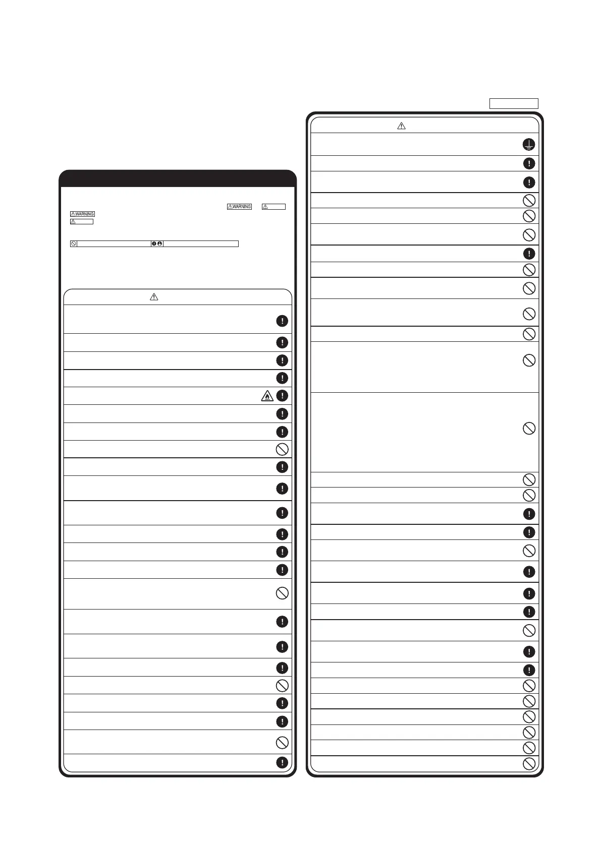
SAFETY PRECAUTIONS
WARNING
CAUTION
●
Read the “SAFETY PRECAUTIONS” carefully first of all and then strictly follow it during the installation work
in order to protect yourself.
●
The precautionary items mentioned below are distinguished into two levels, and .
: Wrong installation would cause serious consequences such as injuries or death.
: Wrong installation might cause serious consequences depending on circumstances.
Both mentions the important items to protect your health and safety so strictly follow them by any means.
●
The meanings of “Marks” used here are as shown on the right:
●
After completing the installation, do commissioning to confirm there are no abnormalities, and explain to the
customers about “SAFETY PRECAUTIONS”, correct operation method and maintenance method (air filter
cleaning, operation method and temperature setting method) with user’s manual of this unit.
Ask your customers to keep this installation manual together with the user’s manual. Also, ask them to hand
over the user’s manual to the new user when the owner is changed.
CAUTION
Never do it under any circumstances.
CAUTION
●
Installation should be performed by the specialist.
If you install the unit by yourself, it may lead to serious trouble such as water leakage, electric shock, fire, and injury due to overturn
of the unit.
●
Install the system correctly according to these installation manuals.
Improper installation may cause explosion, injury, water leakage, electric shock, and fire.
●
Check the density refered by the foumula (accordance with ISO5149).
If the density exceeds the limit density, please consult the dealer and installate the ventilation system.
●
Use the genuine accessories and the specified parts for installation.
If parts unspecified by our company are used it could cause water leakage, electric shock, fire, and injury due to overturn of the unit.
●
Ventilate the working area well in case the refrigerant leaks during installation.
If the refrigerant contacts the fire, toxic gas is produced. In case of R32, the refrigerant could be ignited because of its flammability.
●
Install the unit in a location that can hold heavy weight.
Improper installation may cause the unit to fall leading to accidents.
●
Install the unit properly in order to be able to withstand strong winds such as typhoons, and earthquakes.
Improper installation may cause the unit to fall leading to accidents.
●
Do not mix air in to the cooling cycle on installation or removal of the air-conditioner.
If air is mixed in, the pressure in the cooling cycle will rise abnormally and may cause explosion and injuries.
●
Be sure to have the electrical wiring work done by qualified electrical installer, and use exclusive circuit.
Power source with insufficient capacity and improper work can cause electric shock and fire.
●
Use specified wire for electrical wiring, fasten the wiring to the terminal securely, and hold the cable securely in
order not to apply unexpected stress on the terminal.
Loose connections or hold could result in abnormal heat generation or fire.
●
Arrange the electrical wires in the control box properly to prevent them from rising. Fit the lid of the services
panel property.
Improper fitting may cause abnormal heat and fire.
●
Check for refrigerant gas leakage after installation is completed.
If the refrigerant gas leaks into the house and comes in contact with a fan heater, a stove, or an oven, toxic gas is produced.
●
Use the specified pipe, flare nut, and tools for R32 or R410A.
Using existing parts (R22) could cause the unit failure and serious accident due to explosion of the cooling cycle.
●
Tighten the flare nut according to the specified method by with torque wrench.
If the flare nut were tightened with excess torque, it could cause burst and refrigerant leakage after a long period.
●
Do not put the drainage pipe directly into drainage channels where poisonous gases such as sulfide gas can
occur.
Poisonous gases will flow into the room through drainage pipe and seriously affect the user's health and safety. This can also
cause the corrosion of the indoor unit and a resultant unit failure or refrigerant leak.
●
Connect the pipes for refrigeration circuit securely in installation work before compressor is operated.
If the compressor is operated when the service valve is open without connecting the pipe, it could cause explosion and injuries due
to abnormal high pressure in the system.
●
Stop the compressor before removing the pipe after shutting the service valve on pump down work.
If the pipe is removed when the compressor is in operation with the service valve open, air would be mixed in the refrigeration circuit
and it could cause explosion and injuries due to abnormal high pressure in the cooling cycle.
●
Only use prescribed option parts. The installation must be carried out by the qualified installer.
If you install the system by yourself, it can cause serious trouble such as water leaks, electric shocks, fire.
●
Do not repair by yourself. And consult with the dealer about repair.
Improper repair may cause water leakage, electric shock or fire.
●
Consult the dealer or a specialist about removal of the air-conditioner.
Improper installation may cause water leakage, electric shock or fire.
●
Turn off the power source during servicing or inspection work.
If the power is supplied during servicing or inspection work, it could cause electric shock and injury by the operating fan.
●
Do not run the unit when the panel or protection guard are taken off.
Touching the rotating equipment, hot surface, or high voltage section could cause an injury to be caught in the machine, to get
burned, or electric shock.
●
Shut off the power before electrical wiring work.
It could cause electric shock, unit failure and improper running.
●
Perform earth wiring surely.
Do not connect the earth wiring to the gas pipe, water pipe, lightning rod and telephone earth wiring. Improper earth could
cause unit failure and electric shock due to a short circuit.
●
Earth leakage breaker must be installed.
If the earth leakage breaker is not installed, it can cause electric shocks.
●
Use the circuit breaker of correct capacity. Circuit breaker should be the one that disconnect all
poles under over current.
Using the incorrect one could cause the system failure and fire.
●
Do not use any materials other than a fuse of correct capacity where a fuse should be used.
Connecting the circuit by wire or copper wire could cause unit failure and fire.
●
Do not install the indoor unit near the location where there is possibility of flammable gas leakages.
If the gas leaks and gathers around the unit, it could cause fire.
●
Do not install and use the unit where corrosive gas (such as sulfurous acid gas etc.) or flammable gas (such
as thinner, petroleum etc.) may be generated or accumulated, or volatile flammable substances are handled.
It could cause the corrosion of heat exchanger, breakage of plastic parts etc. And inflammable gas could cause fire.
●
Secure a space for installation, inspection and maintenance specified in the manual.
Insufficient space can result in accident such as personal injury due to falling from the installation place.
●
Do not use the indoor unit at the place where water splashes such as laundry.
Indoor unit is not waterproof. It could cause electric shock and fire.
●
Do not use the indoor unit for a special purpose such as food storage, cooling for precision
instrument, preservation of animals, plants, and a work of art.
It could cause the damage of the items.
●
Do not install nor use the system near equipments which generate electromagnetic wave or high harmonics.
Equipments like inverter equipment, private power generator, high-frequency medical equipment, or telecommunication
equipment might influence the air conditioner and cause a malfunction and breakdown. Or the air conditioner might
influence medical equipments or telecommunication equipments, and obstruct their medical activity or cause jamming.
●
Do not install the remote control at the direct sunlight.
It could cause breakdown or deformation of the remote control.
●
Do not install the indoor unit at the place listed below.
· Places where flammable gas could leak.
· Places where carbon fiber, metal powder or any powder is floated.
·
Place where the substances which affect the air conditioner are generated
such as sulfide gas, chloride gas, acid, alkali or ammonic atmospheres.
· Places exposed to oil mist or steam directly.
· On vehicles and ships
· Places where machinery which generates high harmonics is used.
●
Do not install the indoor unit in the locations listed below (Be sure to install the indoor unit
according to the installation manual for each model because each indoor unit has each limitation)
· Locations with any obstacles which can prevent inlet
and outlet air of the unit
· Locations where vibration can be amplified due to
insufficient strength of structure.
· Locations where the infrared receiver is exposed to
the direct sunlight or the strong light beam. (in case
of the infrared specification unit)
· Locations where an equipment affected by high harmonics
is placed. (TV set or radio receiver is placed within 5m)
· Locations where drainage cannot run off safely.
It can affect performance or function and etc.
.
●
Do not put any valuables which will break down by getting wet under the air conditioner.
Condensation could drop when the relative humidity is higher than 80% or drain pipe is clogged, and it damages user’s belongings.
●
Do not use the base frame for the outdoor unit which is corroded or damaged after a long period of use.
It could cause the unit falling down and injury.
●
Pay attention not to damage the drain pan by weld sputter when brazing work is done near the unit.
If sputter entered into the unit during brazing work, it could cause damage (pinhole) of drain pan and leakage of water.
To avoid damaging, keep the indoor unit packed or cover the indoor unit.
●
Install the drain pipe to drain the water surely according to the installation manual.
Improper connection of the drain pipe may cause dropping water into room and damaging user’s belongings.
●
Do not share the drain pipe for indoor unit and GHP (Gas Heat Pump system) outdoor unit.
Toxic exhaust gas would flow into room and it might cause serious damage (some poisoning or deficiency of oxygen) to
user’s health and safety.
●
Be sure to perform air tightness test by pressurizing with nitrogen gas after completed refrigerant piping work.
If the density of refrigerant exceeds the limit in the event of refrigerant leakage in the small room, lack of oxygen can
occur, which can cause serious accidents.
●
For drain pipe installation, be sure to make descending slope of greater than 1/100, not to make traps,
and not to make air-bleeding.
Check if the drainage is correctly done during commissioning and ensure the space for inspection and maintenance.
●
Ensure the insulation on the pipes for refrigeration circuit so as not to condense water.
Incomplete insulation could cause condensation and it would wet ceiling, floor, and any other valuables.
●
Do not install the outdoor unit where is likely to be a nest for insects and small animals.
Insects and small animals could come into the electronic components and cause breakdown and fire. Instruct the user to
keep the surroundings clean.
●
Pay extra attention, carrying the unit by hand.
Carry the unit with 2 people if it is heavier than 20kg. Do not use the plastic straps but the grabbing place, moving the unit
by hand. Use protective gloves in order to avoid injury by the aluminum fin.
●
Make sure to dispose of the packaging material.
Leaving the materials may cause injury as metals like nail and woods are used in the package.
●
Do not operate the system without the air filter.
It may cause the breakdown of the system due to clogging of the heat exchanger.
●
Do not touch any button with wet hands.
It could cause electric shock.
●
Do not touch the refrigerant piping with bare hands when in operation.
The pipe during operation would become very hot or cold according to the operating condition, and it could cause a burn or frostbite.
●
Do not clean up the air-conditioner with water.
It could cause electric shock.
●
Do not turn off the power source immediately after stopping the operation.
Be sure to wait for more than 5 minutes. Otherwise it could cause water leakage or breakdown.
●
Do not control the operation with the circuit breaker.
It could cause fire or water leakage. In addition, the fan may start operation unexpectedly and it may cause injury.
Always do it according to the instruction.
Do not install the motion sensor mounting panel at following places.
It could cause detection error, incapacity of detection, or
characteristic degradation.
· Place where vibration is applied to it for a long period of
time.
· Place where static electricity or electromagnetic wave
generates.
· Place where it is exposed to high temperature or
humidity
for a long period of time.
·
Dusty place or where the lens face could be fouled or damaged.
· Places where cosmetics or special sprays are
frequently used.
· Highly salted area such as beach.
· Heavy snow area
· Places where the system is affected by
smoke from a chimney.
· Altitude over 1000m
Flat washer (M10)
For unit suspension
8
For unit suspension
[For 2 x 2 grid ceiling] [For ordinary ceiling]
T bar
T bar
Adjust the indoor unit position so that the bottom
surface of the indoor unit is on the same level as
the ceiling's bottom surface.
Adjust the indoor unit position so that the bottom
surface of the indoor unit is on the same level as
the ceiling's bottom surface.
Celling
panel
PJC012D316
 Loading...