-
60
-
'20 • KX-T-347
●The control content of indoor units can be switched in following way.
( is the default setting)
Switch No. control content
SW1 Indoor unit address (tens place)
SW2 Indoor unit address (ones place)
SW3 Outdoor unit address (tens place)
SW4 Outdoor unit address (ones place)
SW5-1 ON Fixed previous version of Superlink protocol
OFF Automatic adjustment of Superlink protocol
SW5-2 Indoor unit address (hundreds place)
SW6-1 ~ 4 Model capacity setting
SW7-1 ON Operation check, Drain motor test run
OFF Normal operation
③④ Operation and confirmation from remote control
⑤ Function of CnT connector of indoor printed circuit board
●XR1-4 are DC 12 V relays. (Equivalent to Omron’s LY2F)
●XR5 is a DC 12 V, 24 V or 100 V relay. (Equivalent to Omron’s MY2F)
●Maker and model of CnT connector (Site side)
Connector : Molex 5264-06
Terminal : Molex 5263T
●CnTA connector is used on FDT, or other. <Check with the specifications.> (Site side) Maker
and model
Connector : J.S.T. Mfg. XAP02V-1-E
Terminal : J.S.T. Mfg. SXA-01T-P0.6
●Output 1 – 4 and input1/2 can be selected/set as required from following items.
Factory default is set as shown below.
1
2
1
2
CNT
(Blue/6P)
+12
CNTA
(Blue/2P)
+12
IndoorPCB
XR1
XR1
XR2
XR3
XR4
XR2
XR3
XR4
XR5
Common
Output 1
Output 2
Output 3
Output 4
Remote ON/OFF switch
or timer contactor
AC100V / 200V
DC12V
DC24V
Input 1
XR6
AC100V / 200V
DC12V
DC24V
Input 2
Note (1) 0.3 mm
2
× 2 m
Note (1) 0.3 mm
2
× 2 m
Note (1) To be no longer than 2 m.
0.75mm
2
× 0.2 m
Butt-connecting contactor
Red
Black
Yellow
Blue
Brown
Orange
Remote ON-OFF/monitor kit
(Applicable range: 0.75 – 1.25 mm
2
)
XR5
XR6
White
Black
Yellow
Blue
Brown
Orange
Orange
●For the setting method, refer to the technical data.
Output
Input
Factory default setting
①
②
③
④
⑤
⑥
⑦
⑧
RUN/STOP
RUN permit prohibition
Emergency stop
Cooling/Heating
Setting temp. shift
Compulsory thermostat OFF
Temporary stop
Silent mode
CnT-2
CnT-3
CnT-4
CnT-5
CnT-6
CnTA
RUN output
Heating output
Compressor ON output
Inspection (error) output
RUN/STOP
RUN/STOP
Output 1
Output 2
Output 3
Output 4
Input 1
Input 2
①
②
③
④
⑤
⑥
⑦
⑧
⑨
⑩
⑪
⑫
⑬
RUN output
Heating output
Compressor ON output
Inspection (error) output
Cooling output
Fan ON output 1
Fan ON output 2
Fan ON output 3
Defrost/oil return output
Ventilation output
Heater output
Free cleaning output
Indoor overload error output
1
2
3
4
5
6
1
2
3
4
5
6
Round crimp terminal
Electric cable
●Electrical wiring work must be performed by an electrician an qualified by a local power
provider. These wiring specifications are determined on the assumption that the following
instructions are observed:
① Do not use cords other than copper ones.
Do not use any supply line lighter than one specified in parentheses for each type below.
-
braided cord (code designation 60245 IEC 51), if allowed in the relevant part 2;
-
ordinary tough rubber sheathed cord (code designation 60245 IEC 53);
-
flat twin tinsel cord (code designation 60227 IEC 41);
-
ordinary polyvinyl chloride sheathed cord (code designation 60227 IEC 53);
② Provide a separate power outlet for each outdoor or indoor unit.
③ All indoor units grouped in one system must have power source that can be turned on or off simultaneously.
④ Pay extra attention so as not to confuse signal line and power source line connection, because an error in their connection
can be burn all the boards at once.
●Connect ground wires before connecting wires between the indoor and outdoor units and
between indoor units. The ground wires need to be longer than the wires between the
indoor and outdoor units, and protected from undue stress.
●Do not turn on the power source before completing the work.
●The ground wires must be connected by the Class D grounding connection.
●Use the round crimp terminals for connections to the terminal block.
●Use dedicated branch circuits, avoiding combination with other devices. Otherwise, it
could trip the power source breaker, resulting in secondary accidents.
●Install the overcurrent and earth leakage breakers specified to respective models.
●Do not connect indoor and outdoor signal cables to extension cables on the way. If the
joint is wetted with intruding water, it could cause a ground insulation failure or poor
connection, resulting in communication errors. (If it is inevitable to connect cables on the
way, make sure to prevent the water intrusion completely.)
●When running wires (wires for power supply, remote control, connecting between
indoor and outdoor units, or other) behind the ceiling, protect them using copper or other
pipes against assault by rat, or other.
●
It is up to 3.5 mm
2
the size of power source cables connected to indoor units. When using cables
of 5.5 mm
2
or larger, provide a dedicated pull box for branching connection to indoor units.
●If signal and power
source
cables are connected mistakenly, it could burn down all PCBs.
① Even if the power source of 220/240/380/415 V is connected mistakenly to A-B signal cable, it is protected at initial occasion
only.
② If the remote control fails to detect the unit No. (address) at 15 minutes after turning the power on, check and repair all
signal cables for misconnection.
③ Cut the jumper wire J10SL1 of burnt PCB, and reconnect connectors CnK (yellow) and CnK1 (white) to CnK2 (black).
④ If any anomaly is found on wires between the A-B terminal block and the PCB, replace them.
●At the outside of indoor and outdoor units, take care to avoid direct contacts between
remote control and power source cables.
●In no event connect the power source of 220/240/380/415 V to the remote control
terminal block. It could cause failures.
●Connections of wiring between units, ground wire and remote controller cable
① When connecting wires between units, ground wire or remote control wire, connect them according to the number of
terminals on the power source terminal block or signal terminal block in the control box. Connect the ground wire to the
ground terminal on the power source terminal block.
② Make sure to install an earth leakage breaker for the power source. Select a breaker for inverter circuit.
③ When the earth leakag
e breaker is exclusive for the earth leakage protection, it is necessary to connect also an isolating
switch (Switch + Class B fuse) or wiring circuit breaker in series to the earth leakage breaker.
④ Install the isolating switch close to the unit.
●Connect wires securing by tightening screws firmly. Confirm also no connector or wire
(from terminal) is disconnected in the control box.
●
When installing an auxiliary electric heater, consult the electric heater manual or technical data.
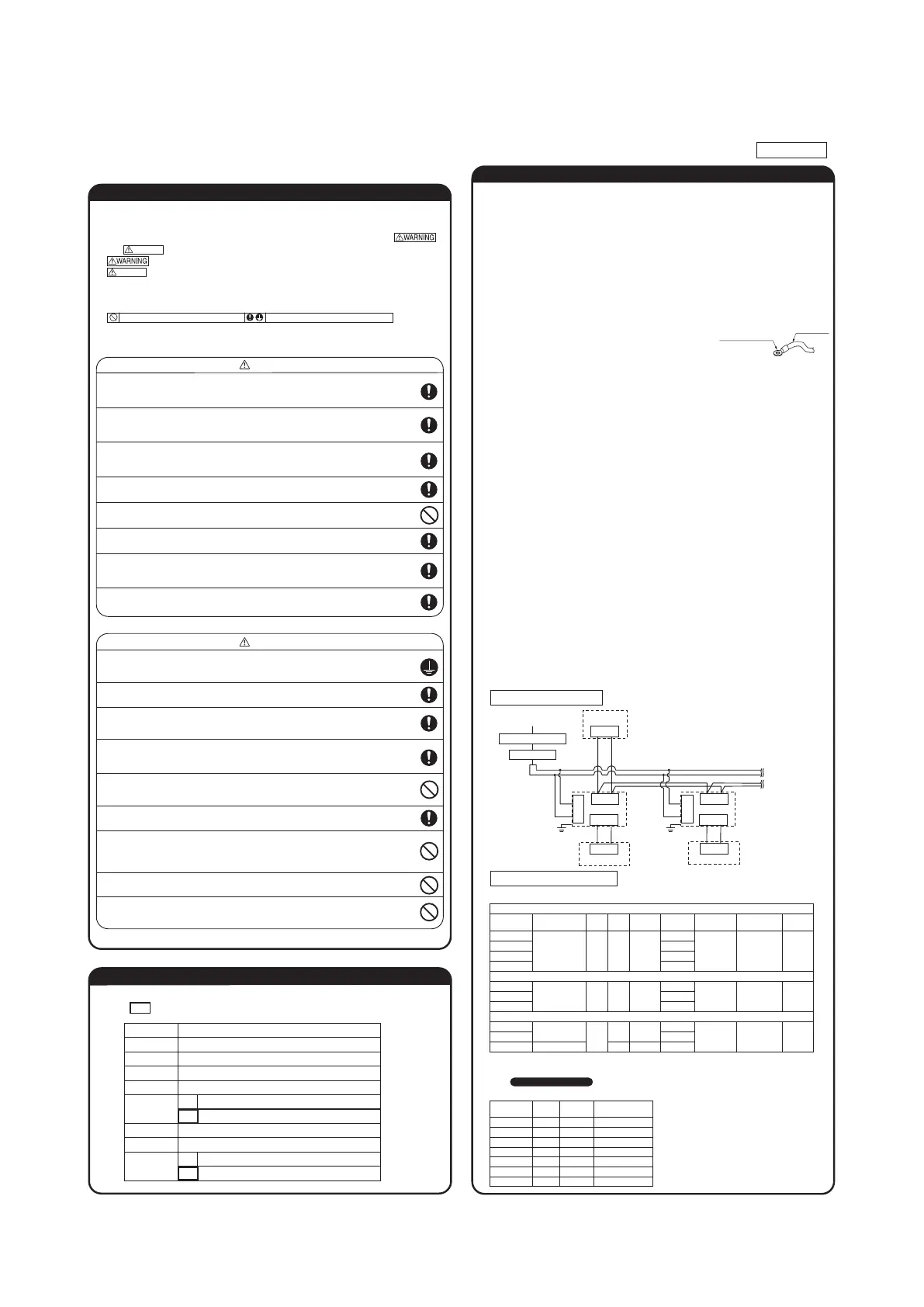
Cabling system diagram (Outdoor/indoor unit connection procedure)
Ⓐ Ⓑ
Ⓐ Ⓑ
Ⓧ Ⓨ
Ⓛ
Ⓝ
Ⓧ Ⓨ
Ⓐ Ⓑ
Ⓧ Ⓨ
Ⓛ
Ⓝ
Ⓧ Ⓨ
Outdoor unit
Power source
Indoor unit1 Indoor unit2
Signal line (between indoor and outdoor units)
Earth
Signal line
(between indoor unit)
Earth
Remote control
Remote
control line
Remote
control line
Remote control
●
Be sure to have the electrical wiring work done by qualified electrical installer,
and use exclusive circuit.
Power source with insufficient capacity and improper work can cause electric shock and fire.
●
Use specified wire for electrical wiring, fasten the wiring to the terminal securely,
and hold the cable securely in order not to apply unexpected stress on the terminal.
Loose connections or hold could result in abnormal heat generation or fire.
●Arrange the electrical wires in the control box properly to prevent them from
rising. Fit the lid of the services panel property.
Improper fitting may cause abnormal heat and fire.
●
Use the genuine option parts. And installation should be performed by a specialist.
If you install the unit by yourself, it could cause water leakage, electric shock and fire.
●Do not repair by yourself. And consult with the dealer about repair.
Improper repair may cause water leakage, electric shock or fire.
●Consult the dealer or a specialist about removal of the air-conditioner.
Improper installation may cause water leakage, electric shock or fire.
●Turn off the power source during servicing or inspection work.
If the power is supplied during servicing or inspection work, it could cause electric shock and injury by
the operating fan.
●Shut off the power before electrical wiring work.
It could cause electric shock, unit failure and improper running.
●Perform earth wiring surely.
Do not connect the earth wiring to the gas pipe, water pipe, lightning rod and telephone earth wiring.
Improper earth could cause unit failure and electric shock due to a short circuit.
●Earth leakage breaker must be installed.
If the earth leakage breaker is not installed, it can cause electric shocks.
●Make sure to install earth leakage breaker on power source line.
(countermeasure thing to high harmonics.)
Absence of breaker could cause electric shock.
●Use the circuit breaker of correct capacity. Circuit breaker should be the one
that disconnect all poles under over current.
Using the incorrect one could cause the system failure and fire.
●Do not use any materials other than a fuse of correct capacity where a fuse
should be used.
Connecting the circuit by wire or copper wire could cause unit failure and fire.
●Use power source line of correct capacity.
Using incorrect capacity one could cause electric leak, abnormal heat generation and fire.
●Do not mingle solid cord and stranded cord on power source and signal side
terminal block.
In addition, do not mingle difference capacity solid or stranded cord.
Inappropriate cord setting could cause loosing screw on terminal block, bad electrical contact, smoke and fire.
●Do not turn off the power source immediately after stopping the operation.
Be sure to wait for more than 5 minutes. Otherwise it could cause water leakage or breakdown.
●Do not control the operation with the circuit breaker.
It could cause fire or water leakage. In addition, the fan may start operation unexpectedly and it may
cause injury.
Security instructions
WARNING
CAUTION
Address setting is done by (1) Manual address setting or (2) Automatic address setting.
In the case of (2) "Automatic address setting", it is possible to change address setting by wired
remote control after once complete setting.
As for details of setting procedure, refer to instructions attached to the outdoor unit for details.
② Address setting
① Electrical Wiring Connection (continued)
Ⓧ Ⓨ
Ⓧ Ⓨ
Ⓧ Ⓨ
Ⓐ Ⓑ
Ⓐ Ⓑ
Ⓧ Ⓨ
Ⓐ Ⓑ
Ⓐ Ⓑ
Ⓧ Ⓨ
Ⓐ Ⓑ
Ⓧ Ⓨ
Ⓐ Ⓑ
Ⓧ Ⓨ
Ⓐ Ⓑ
Ⓧ Ⓨ
Ⓐ Ⓑ
Ⓧ Ⓨ
Ⓧ Ⓨ
① A remote control can control plural indoor units (up to 16)
In above setting, all plural indoor units will operate under same mode and temperature setting.
② Connect all indoor units with 2 core remote control line for group control.
③ Use the function of manual address setting to set the indoor and outdoor address number.
○Do not forget to set the number for the outdoor units.
④
As shown in the following figure, the remote control can be used to control multiple outdoor units.
⑤ One remote control is able to perform group control for multiple units (maximum 16 units).
○Use the rotary SW1 and SW2 provided on the indoor unit PCB (Printed circuit board) to set unique remote control
communication address avoiding duplication.
Outdoor unit
No.01
Outdoor unit
No.02
Indoor unit Indoor unit
Outdoor No.01
Indoor No.01
Indoor unit Indoor unit
Indoor unit
Indoor unit
Remote control
Indoor unit
Remote control
SW1” Master”
Remote control
SW1” Slave”
Master
Slave
Slave remote
control
Wired remote control: SW1
Wireless kit: SW1-2
Master remote
control
Outdoor No.02
Indoor No.04
Outdoor No.01
Indoor No.02
Outdoor No.02
Indoor No.05
Outdoor No.01
Indoor No.03
Outdoor No.02
Indoor No.06
● Do not install it on the following places.
(1) Place exposed to direct sunlight (4) Hot surface or cold surface enough to generate condensation
(2) Places near heat devices (5) Place exposed to oil mist or steam directly.
(3) High humidity places (6) Uneven surface
③ Remote Control, Wiring and functions
① Install remote control referring to the attached manual.
② Wiring of remote control should use 0.3mm
2
x2 core wires or cables.
The insulation thickness is 1mm or more. (on-site configuration)
③ Maximum prolongation of remote control wiring is 600 m.
If the prolongation is over 100m, change to the size below.
But, wiring in the remote control case should be under 0.5mm
2
. Change the wire size outside of the case
according to wire connecting. Waterproof treatment is necessary at the wire connecting section. Be careful about
contact failure.
100-200m ...................0.5mm
2
×2 core
Under 300m................0.75mm
2
× 2 core
Under 400m................1.25mm
2
× 2 core
Under 500m................2.0mm
2
× 2 core
④ Avoid using multi-core cables to prevent malfunction.
⑤ Keep remote control line away from earth (frame or any metal of building).
⑥
Make sure to connect remote control line to the remote control and terminal block of
indoor unit. (No polarity)
Remote control line
(No polarity)
Remote control
line
(No polarity)
Electrical wiring work must be performed by an electrician qualified by a local power provider according to
the electrical installation technical standards and interior wiring regulations applicable to the installation site.
Earth leakage breaker
Circuit breaker
●When connecting indoor units to the power source individually:
① Electrical Wiring Connection
●
●
●
●
Read the “SAFETY PRECAUTIONS” carefully first of all and then strictly follow it during the
installation work in order to protect yourself.
The precautionary items mentioned below are distinguished into two levels,
and .
:
Wrong installation would cause serious consequences such as injuries or death.
:
Wrong installation might cause serious consequences depending on circumstances.
Both mentions the important items to protect your health and safety so strictly follow
them by any means.
The meanings of “Marks” used here are as shown on the right:
Accord with following items. Otherwise, there will be the risks of electric shock and
fire caused by overheating or short circuit.
Never do it under any circumstances.
CAUTION
CAUTION
Always do it according to the instruction.
Installation and wiring of remote control
Control plural indoor units by a single remote control
A maximum of two remote control units can be connected to one indoor unit (or one group of indoor units.)
Latest "function setting" is superior than previous one.
Acceptable combination is "two (2) wired remote controls", "one (1) wired remote control and one (1) wireless
kit" or "two (2) wireless kits".
Set one to “Master” and the other to “Slave”.
Note:The setting "Remote control unit sensor enabled" is only selectable with the master remote control unit in the
position where you want to check room temperature.
Master/slave setting when more than one remote control unit are used
Control mode switching
Power source specifications
① Use of indoor unit’s power source (Models other than ② – ③)
② High static pressure duct, suction air processing unit, outdoor air processing unit with humidifier
③ Floor type system package
Model
capacity
Switch
capacity
Fuse
Power source
wire size
Wire
length
Signal
cable
Remote control
cable
Ground
wire
Leakage breaker
rating
22-36 types
45-56 types
71-90 types
112-160 types
298m
275m
179m
123m
45-90 types
112-160 types
224, 280 types
149m
85m
28m
15A 30mA 0.1sec 30A 15A 2.0mm
2
×2 2.0mm
2
0.3mm
2
×2-core
0.75~1.25mm
2
×2
30A 15A 2.0mm
2
×2 2.0mm
2
0.3mm
2
×2-core
0.75~1.25mm
2
×2
112 types
140, 160 types
224, 280 types
51m
34m
32m
30A
15A
20A
2.0mm
2
×2
3.5mm
2
×2
2.0mm
2
0.3mm
2
×2-core
0.75~1.25mm
2
×2
15A 30mA 0.1sec
15A 30mA 0.1sec
20A 30mA 0.1sec
Model Coefficient
FDT, FDTC
FDTW, FDTS, FDR, FDU, FDE, FDK, FDU-F
Other
3.5
2.5
1
Note 1. The wire length is calculated with a voltage drop of 2%. If the wire length should exceed the above data, review the wire size to
use in accordance with extension wire regulations in your country.
Note 2. When total length of remote control cable is longer than 100 m, review the cable size according to
③ Remote control installation .
Note 3. Following equation is a guide which could vary depending on the equipment at site and contents of installation work. When the
leakage breaker trips frequently, select a breaker suitable to these conditions.
For the rated sensitivity current of leakage breaker, refer to the following equation and judgment method.
<Equation> Necessary sensitivity current =
Total value of (Model coefficient of each indoor unit × Number of units) + (Wire coefficient × Wire length [km])
<Model coefficient>
<Judgment method>
Power source wire size Coefficient
2.0mm
2
3.5mm
2
5.5mm
2
8.0mm
2
50
60
60
60
<Wire coefficient>
* Following judgment method is for reference. Allowance of leakage current and capacity of rated sensitivity
current should be selected according to applicable standards in your country.
( i ) Necessary sensitivity current ≦ 30
( ii ) 30 < Necessary sensitivity current ≦ 100
(iii) 100 < Necessary sensitivity current
Use a product of rated sensitivity current at 30 mA (0.1 s or less).
Divide the leakage breaker system, in principle, so that the necessary sensitivity
current will become less than 30 mA.
Depending on the situation of installation (according to standards in respective
countries), it may be possible to use a product of rated sensitivity current at 100
mA (0.15 or less).
It is necessary to divide (add) the leakage breaker system.
●When connecting multiple indoor units to one power source:
Total current
of indoor units
Wire length
(m)
Rated current of
wiring leakage breaker
Wire size
(mm
2
)
< 7A
< 11A
< 12A
< 16A
< 19A
< 22A
< 28A
2
3.5
5.5
5.5
5.5
8
8
21
21
33
24
20
27
21
20A
20A
20A
30A
40A
40A
50A
Note 1. Wire length in the able is applicable when indoor units
are connected in series. Wire size and length for each
range of total current of indoor units are calculated
with a voltage drop of less than 2%. If the current
should exceed values in the left table, review the wire
size to use in accordance with extension wire
regulations in your country.
Note 2. During servicing (when the power source is turned
off), refrain from taking power for indoor units in other
refrigerant pipe system from the same power source.
In case of Heat recovery 3-pipe systems
Branching controller of heat recovery 3-pipe systems wiring
●When this unit is used as a "Heat Recovery 3-pipe Systems", refer to the installation manual of a
branching controller (option).
Switch Setting Contents
No. Item
Operation from the eco touch remote
control (RC-EX series)
Operation from the standard remote
control (RC-E4, RC-E series)
1 Check the number
of units connected
in the multi remote
control system.
[Menu]
⇒
[Service setting]
⇒
[Service & Maintenance]
⇒
[Service password]
⇒
[IU address]
①
Press the
AIR CON NO
button to display
the IU address.
②
Press the
button and check
addresses of connected indoor units one
by one.
2 Check if each unit is
connected properly
in the remote
control system.
[Menu]
⇒
[Service setting]
⇒
[Service & Maintenance]
⇒
[Service password]
⇒
[IU address]
⇒
[Check run mode]
①
Press the
AIR CON NO
button to display
the IU address.
②
Press the
button and select one
of IU addresses.
③
Press the
(MODE) button. The unit
starts to blow air.
3 Setting main/sub
remote controls
[Menu]
⇒
[Service setting]
⇒
[R/C function settings]
⇒
[Service password]
⇒
[Main/Sub of R/C]
Set SW1 to “Sub” for the sub remote control
unit.
4 Checking operation
data
[Menu]
⇒
[Service setting]
⇒
[Service & Maintenance]
⇒
[Service password]
⇒
[Operation data]
Press the
”
is displayed.
⇒
Press the
” is displayed.
⇒
Select one
of addresses for connected indoor units
by pressing the
” is
displayed.
⇒
Select data by pressing the
button.
5 Checking inspection
display
[Menu]
⇒
[Service setting]
⇒
[Service & Maintenance]
⇒
[Service password]
⇒
[Error display]
Press the
” is
displayed.
⇒
Press the
” is displayed.
⇒
Press
the
” is
displayed.
⇒
Data is displayed.
6 Cooling test run
from remote
control
[Menu]
⇒
[Service setting]
⇒
[Installation settings]
⇒
[Service password]
⇒
[Test run]
⇒
[Cooling test run]
⇒
[Start]
①
Start the system by pressing the
(MODE)
button.
③
Press the
button for 3 seconds or
longer. The screen display will switch to
“
(SET) button, while the
“
” is displayed, starts the
cooling test run. The screen display will
switch to “
”.
7 Trial operation of
drain pump from
remote control
[Menu]
⇒
[Service setting]
⇒
[Installation settings]
⇒
[Service password]
⇒
[Test run]
⇒
[Drain pump test run]
⇒
[Run]
①
Start the system by pressing the
button. The display will change
to “
(SET) button starts the
drain pump operation. The display will
show “
”.
The menu configuration may vary depending on models of the remote control. If the model of your
remote control is different, refer to the installation manual attached to the remote control.
PSC012D118
9.2 Electric wiring work instruction
 Loading...