-
106
-
'14 • KX-T-222
9.3 Instruction of how to replace PCB
SAFETY PRECAUTIONS
WARNING
CAUTION
WARNING
CAUTION
PSB012D991B
● Read the "SAFETY PRECAUTIONS" carefully first of all and then strictly follow it during the replacement in order to protect yourself.
● The precautionary items mentioned below are distinguished into two levels, WARNING and CAUTION.
Both mentions the important items to protect your health and safety so strictly follow them by any means.
Wrong installation would cause serious consequences such as injuries or death.
Wrong installation might cause serious consequences depending on circumstances.
● After completing the replacement, do commissioning to confirm there are no abnormalities.
● Replacement should be performed by the specialist.
If you replace the PCB by yourself, it may lead to serious trouble such as electric shock or fire.
● Replace the PCB correctly according to these instructions.
Improper replacement may cause electric shock or fire.
● Shut off the power before electrical wiring work. Start the work after elapsing 1 minutes or more from power off.
Replacement during the applying the current would cause the electric shock, unit failure or improper running.
It would cause the damage of connected equipment such as fan motor,etc.
● Fasten the wiring to the terminal securely, and hold the cable securely so as not to apply unexpected stress on the terminal.
Loose connections or hold could result in abnormal heat generation or fire.
● Check the connection of wiring to PCB correctly before turning on the power, after replacement.
Defectiveness of replacement may cause electric shock or fire.
● In connecting connector onto the PCB, connect not to deform the PCB. It may cause breakage or malfunction.
● Insert connector securely, and hook stopper. It may cause fire or improper running.
● Bundle the cables together so as not to be pinched or be tensioned. It may cause malfunction or electric shock for disconnection
or deformation.
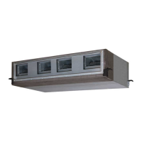
Models : FDU224KXZE1, 280KXZE1
FDU650FKXZE1, 1100FKXZE1, 1800FKXZE1, 2400FKXZE1
(1) Control PCB
Replace and set up the PCB according to this instruction.
(1) Set to an appropriate address and function using switch on PCB.
Select the same setting with the remo ved PCB.
(2) Set to an appropriate capacity using the model selector switches (SW6, 8 and J1).
Select the same setting with the remo ved PCB.
Setting
SW8
Setting
SW8
Setting
SW8
model -1 -2 -3 -4 -1 model -1 -2 -3 -4 -1 model -1 -2 -3 -4 -1
SW6 SW8
15
- - - -
〇
OP EN
P50
〇
-
〇
- -
OPEN
112
〇 〇
-
〇
-
OP EN
ON ON
22
- - - - -
OP EN
56
-
〇 〇
- -
OP EN
140
- -
〇 〇
-
OP EN
28
〇
- - - -
OP EN
P63
〇 〇 〇
- -
OPEN
160
〇
-
〇 〇
-
OP EN
36
-
〇
- - -
OP EN
71
- - -
〇
-
OP EN
224
-
〇 〇 〇
-
OP EN
1 2 3 4 1 2 3 4
P40
〇 〇
- - - - -
280
〇 〇 〇 〇
-
OP EN
45
- -
〇
- -
OP EN
90
-
〇
-
〇
-
OP EN
Example setting for 56
 Loading...