③ Remote Control, Wiring and functions (continued)
④ Operation and confirmation from remote control
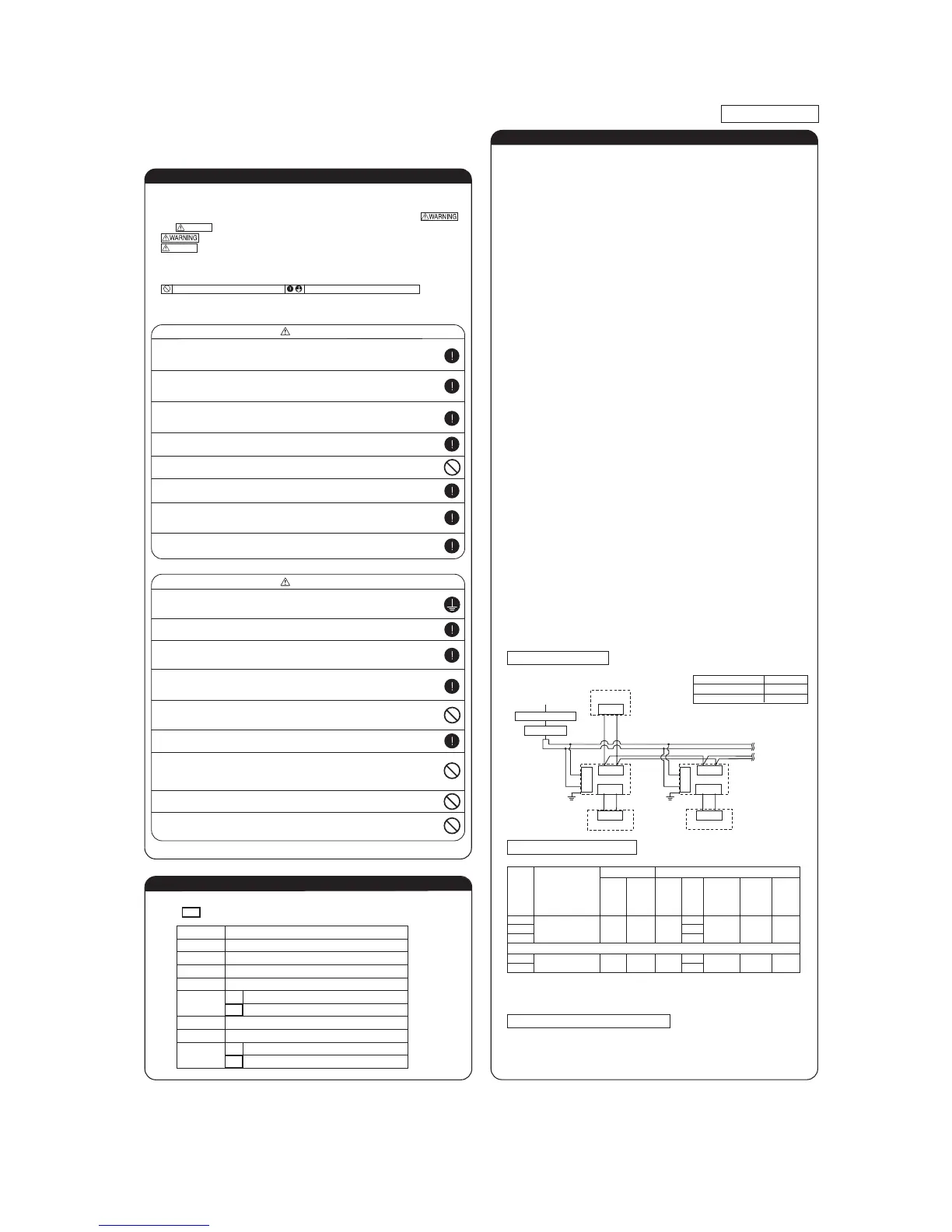
⑤ Function of CNT connector of indoor printed circuit board
1
2
1
2
3
4
5
6
1
2
1
2
3
4
5
6
Red
CNT
(Blue 6P)
+12
CNTA
(Blue 2P)
+12
Indoor units control box
Black
XR1
XR1
XR2
XR3
XR4
XR2
XR3
XR5
XR6
XR4
XR5
Yellow
Blue
Brown
Orange
White
Black
Yellow
Blue
Brown
Orange
Orange
Common
Output 1
Output 2
Output 3
Output 4
Remote start/stop
button or timer point
AC100V
DC12V
DC24V
Input
power 1
Input
power 2
XR6
AC100V
DC12V
DC24V
Note(1)0.3mm
2
×2m
Note(1)0.3mm
2
×2m
Note (1): Do not use the length over 2 meter
Printed circuit board
Remote start/stop kit
0.75mm
2
×0.2m
Butt splice
(Application coverage
0.75〜1.25mm
2
)
●CNT connector (local) vendor model
Connector : Made by molex 5264-06
Terminals : Made by molex 5263 T
●CNTA connector is installed on FDT, etc. Refer to the spec. drawings.
CNTA connector (local) vendor model
Connector : Made by JST XAP02V-1-E
Terminals : Made by JST SXA-01T-P0.6
●Function
* Refer to I/U settings.
Output 1 Air-conditioner operation output (When the air-conditioner ON: XR1 = ON)
Output 2 Heating output
Output 3 Thermostat ON output (When the thermostat ON: XR3 = ON)
Output 4 Air-conditioner check ON (When checking air-conditioner: XR4 = ON)
XR5 OFF ⇒ ON: Air-conditioner operates.
At shipping
XR5 ON ⇒ OFF: Air-conditioner stops.
*Functions and controls may vary depending on the switching at site.
Input
XR6 OFF ⇒ ON: Air-conditioner operates.
At shipping
XR6 ON ⇒ OFF: Air-conditioner stops.
*Functions and controls may vary depending on the switching at site.
Input 2
(FDT etc.)
Press the CHECK button. ⇒ “ ” is displayed. ⇒
Press the (SET) button. ⇒ “ ” is displayed. ⇒
“ ” is dispayed. ⇒ Select one of addresses
for connected indoor units by pressing the
or
button.
⇒ Press the (SET) button. ⇒ “ ” is displayed.
⇒ Select data by pressing the
or
button.
Press the
CHECK
button. ⇒ Press the button. ⇒
“ ” is dispayed. ⇒ Press the (SET) button.
⇒ “ ” is displayed. ⇒
Select data by pressing the
or
button.
Ⓧ Ⓨ
Ⓧ Ⓨ
Ⓧ Ⓨ
Ⓐ Ⓑ
Ⓐ Ⓑ
Ⓧ Ⓨ
Ⓐ Ⓑ
Ⓐ Ⓑ
Ⓧ Ⓨ
Ⓐ Ⓑ
Ⓧ Ⓨ
Ⓐ Ⓑ
Ⓧ Ⓨ
Ⓐ Ⓑ
Ⓧ Ⓨ
Ⓐ Ⓑ
Ⓧ Ⓨ
Ⓧ Ⓨ
●Electrical wiring work must be performed by an electrician an qualified by a local power
provider. These wiring specifications are determined on the assumption that the following
instructions are observed:
① Do not use cords other than copper ones.
Do not use any supply line lighter than one specified in parentheses for each type below.
-
braided cord (code designation 60245 IEC 51), if allowed in the relevant part 2;
-
ordinary tough rubber sheathed cord (code designation 60245 IEC 53);
-
flat twin tinsel cord (code designation 60227 IEC 41);
-
ordinary polyvinyl chloride sheathed cord (code designation 60227 IEC 53);
② Provide a separate power outlet for each outdoor or indoor unit.
③ All indoor units grouped in one system must have power source that can be turned on or off simultaneously.
④ Pay extra attention so as not to confuse signal line and power source line connection, because an error in their connection
can be burn all the boards at once.
●Screw the line to terminal block without any looseness, certainly.
●Do not turn on the switch of power source, before all of line work is done.
●Provide a dedicated branching circuit and never share a branching circuit with other
equipment. If shared, disconnection at the circuit breaker may occur, which can cause
secondary damage.
●Install an over-current and earth leakage breaker (threshold current: 30mA) specified for
each unit without fail.
●Set earth of D-type.
●
Do not connect the power source line [220V/240V/380V/415V] to signal side terminal
block. Otherwise, it could cause failure.
●
Run the lines (power source, remote controller and "between indoor and outdoor unit")
upper ceiling through iron pipe or other tube protection to avoid the damage by mouse
and so on.
●
Connection of a cable beyond 3.5 mm
2
is not permitted. When cables of over 5.5 mm
2
are
in use, provide a dedicated pull box to take a branch to an indoor unit.
●Misconnection between signal wires and power source wires could burn out all PCBs.
Connect them carefully.
① Even if 200 V power source is connected mistakenly to signal wire A or B, PCBs are protected at the first time only.
② If you cannot confirm a unit No. (address) from the remote control 15 minutes after turning the power on, check all signal
wires and correct misconnection(s).
③ Cut off the jumper wire J 10SL1 on the burn-out PCB and replace connectors CnK (yellow) and CnK1 (white) with Cnk2
(black).
④ If there is any anomaly in the wiring from A or B terminal block to the PCB, replace the wiring.
●
Keep "remote control line" and "power source line" away from each other on constructing
of unit outside.
●
Do not add cord in the middle of line (of indoor power source, remote control and signal)
route on outside of unit. If connecting point is flooded, it could cause problem as for electric
or communication.
(In the case that it is necessary to set connecting point on the signal line way, perform
thorough waterproof measurement.)
●Connection of the line ("Between indoor and outdoor unit", Earth and Remote control)
① Remove lid of control box before connect the above lines, and connect the lines to terminal block according to number
pointed on label of terminal block.
I
n addition, pay enough attention to confirm the number to lines, because there is electrical polarity except earth line.
Furthermore, connect earth line to earth position of terminal block of power source.
②
Install earth leakage breaker on power source line. In addition, select the type of breaker for inverter circuit as earth leakage
breaker.
③
If the function of selected earth leakage breaker is only for earth-fault protection, hand switch (switch itself and type "B" fuse) or
circuit breaker is required in series with the earth leakage breaker.
④
Install isolator or disconnect switch on the power supply wiring in accordance with the local codes and regulations.
The isolator should be set in the box with key to prevent touching by another person when servicing.
Cabling system diagram (Outdoor/indoor unit connection procedure)
Ⓐ Ⓑ
Outdoor unit
Power source
Indoor unit1 Indoor unit2
Signal line (between indoor and outdoor units)
Use shielded cord for a signal line and connect “earth
(signal line)” at all the indoor units and
outdoor units.
Earth
Signal line
(between indoor unit)
Earth
Remote control
Remote
control line
Remote
control line
Power source line specification
Note (1) The cord distances are calculated with a voltage drop of 2%. If the distance should exceed the
above data, review the cord thickness to use in accordance with your extension cord regulations.
(2) When total extension of remote control line is more than 100m, change the size of cord
according to "③ Remote Control, Wiring and functions".
In case of Heat recovery 3-pipe systems
Branching controller of heat recovery 3-pipe systems wiring
●When this unit is used as a "Heat Recovery 3-pipe Systems", refer to the installation
manual of a branching control (option).
Control plural indoor units by a single remote control
① A remote control can control plural indoor units (up to 16)
In above setting, all plural indoor units will operate under same mode and temperature setting.
② Connect all indoor units with 2 core remote control line for group control.
③ Use the function of manual address setting to set the indoor and outdoor address number.
○Do not forget to set the number for the outdoor units.
④ As shown in the following figure, the remote control can be used to control multiple outdoor
units.
⑤ One remote control is able to perform group control for multiple units (maximum 16 units).
○Use the rotary SW1 and SW2 provided on the indoor unit PCB (Printed circuit board) to set unique remote control
communication address avoiding duplication.
Outdoor unit
No.01
Outdoor unit
No.02
Indoor unit Indoor unit
Outdoor No.01
Indoor No.01
Indoor unit Indoor unit
Indoor unit
Indoor unit
Remote control
Indoor unit
Remote control
SW1” Master”
Remote control
SW1” Slave”
Switch Setting Contents
Master
Slave
Slave remote
control
Wired remote control: SW1
Wireless kit: SW1-2
Master remote
control
Master/slave setting when more than one remote control unit are used
A maximum of two remote control units can be connected to one indoor unit (or one group of
indoor units.)
Latest "function setting" is superior than previous one.
Acceptable combination is "two (2) wired remote controls", "one (1) wired remote control and
one (1) wireless kit" or "two (2) wireless kits".
Set one to “Master” and the other to “Slave”.
Note:The setting "Remote control unit sensor enabled" is only selectable with the master
remote control unit in the position where you want to check room temperature.
Remote control
Outdoor No.02
Indoor No.04
Outdoor No.01
Indoor No.02
Outdoor No.02
Indoor No.05
Outdoor No.01
Indoor No.03
Outdoor No.02
Indoor No.06
●
Be sure to have the electrical wiring work done by qualified electrical installer,
and use exclusive circuit.
Power source with insufficient capacity and improper work can cause electric shock and fire.
●
Use specified wire for electrical wiring, fasten the wiring to the terminal securely,
and hold the cable securely in order not to apply unexpected stress on the terminal.
Loose connections or hold could result in abnormal heat generation or fire.
●Arrange the electrical wires in the control box properly to prevent them from
rising. Fit the lid of the services panel property.
Improper fitting may cause abnormal heat and fire.
●
Use the genuine option parts. And installation should be performed by a specialist.
If you install the unit by yourself, it could cause water leakage, electric shock and fire.
●Do not repair by yourself. And consult with the dealer about repair.
Improper repair may cause water leakage, electric shock or fire.
●Consult the dealer or a specialist about removal of the air-conditioner.
Improper installation may cause water leakage, electric shock or fire.
●Turn off the power source during servicing or inspection work.
If the power is supplied during servicing or inspection work, it could cause electric shock and injury by
the operating fan.
●Shut off the power before electrical wiring work.
It could cause electric shock, unit failure and improper running.
●Perform earth wiring surely.
Do not connect the earth wiring to the gas pipe, water pipe, lightning rod and telephone earth wiring.
Improper earth could cause unit failure and electric shock due to a short circuit.
●Earth leakage breaker must be installed.
If the earth leakage breaker is not installed, it can cause electric shocks.
●Make sure to install earth leakage breaker on power source line.
(countermeasure thing to high harmonics.)
Absence of breaker could cause electric shock.
●Use the circuit breaker of correct capacity. Circuit breaker should be the one
that disconnect all poles under over current.
Using the incorrect one could cause the system failure and fire.
●Do not use any materials other than a fuse of correct capacity where a fuse
should be used.
Connecting the circuit by wire or copper wire could cause unit failure and fire.
●Use power source line of correct capacity.
Using incorrect capacity one could cause electric leak, abnormal heat generation and fire.
●Do not mingle solid cord and stranded cord on power source and signal side
terminal block.
In addition, do not mingle difference capacity solid or stranded cord.
Inappropriate cord setting could cause loosing screw on terminal block, bad electrical contact, smoke and fire.
●Do not turn off the power source immediately after stopping the operation.
Be sure to wait for more than 5 minutes. Otherwise it could cause water leakage or breakdown.
●Do not control the operation with the circuit breaker.
It could cause fire or water leakage. In addition, the fan may start operation unexpectedly and it may
cause injury.
Security instructions
WARNING
CAUTION
Address setting is done by (1) Manual address setting or (2) Automatic address setting.
In the case of (2) "Automatic address setting", it is possible to change address setting by wired
remote control after once complete setting.
As for details of setting procedure, refer to instructions attached to the outdoor unit for details.
Installation and wiring of remote control
② Address setting
● Do not install it on the following places.
(1) Place exposed to direct sunlight (4) Hot surface or cold surface enough to generate condensation
(2) Places near heat devices (5) Place exposed to oil mist or steam directly.
(3) High humidity places (6) Uneven surface
③ Remote Control, Wiring and functions
① Install remote control referring to the attached manual.
② Wiring of remote control should use 0.3mm
2
x2 core wires or cables.
The insulation thickness is 1mm or more. (on-site configuration)
③ Maximum prolongation of remote control wiring is 600 m.
If the prolongation is over 100m, change to the size below.
But, wiring in the remote control case should be under 0.5mm
2
. Change the wire size outside of the case
according to wire connecting. Waterproof treatment is necessary at the wire connecting section. Be careful about
contact failure.
100-200m ...................0.5mm
2
×2 core
Under 300m................0.75mm
2
× 2 core
Under 400m................1.25mm
2
× 2 core
Under 500m................2.0mm
2
× 2 core
④ Avoid using multi-core cables to prevent malfunction.
⑤ Keep remote control line away from earth (frame or any metal of building).
⑥
Make sure to connect remote control line to the remote control and terminal block of
indoor unit. (No polarity)
Remote control line
(No polarity)
Remote control line
(No polarity)
Electrical wiring work must be performed by an electrician qualified by a local power provider according to
the electrical installation technical standards and interior wiring regulations applicable to the installation site.
Earth leakage breaker
Circuit breaker
Wiring specification
① Electrical Wiring Connection
PSC012D001
●
●
●
●
Read the “SAFETY PRECAUTIONS” carefully first of all and then strictly follow it during the
installation work in order to protect yourself.
The precautionary items mentioned below are distinguished into two levels,
and .
:
Wrong installation would cause serious consequences such as injuries or death.
:
Wrong installation might cause serious consequences depending on circumstances.
Both mentions the important items to protect your health and safety so strictly follow
them by any means.
The meanings of “Marks” used here are as shown on the right:
Accord with following items. Otherwise, there will be the risks of electric shock and
fire caused by overheating or short circuit.
Never do it under any circumstances.
CAUTION
CAUTION
Always do it according to the instruction.
Operation from RC-EX1
1 Check the number of units connected in the multi remote control system.
“Menu”⇒“Next”⇒“Service & Maintenance”⇒
“Input password”⇒“IU address”
2 Check if each unit is connected properly in the remote control system.
When the operation is stopped,“Menu”⇒
“Next”⇒“Service & Maintenance”⇒
“Input password”⇒”IU address”⇒”check run mode”
3 Setting master/slave remote controls
“Menu”⇒“Next”⇒“R/C function settings”⇒
“Input password”⇒“Main/Sub of R/C”
4 Checking operation data
“Menu”⇒“Next”⇒“Service & Maintenance”⇒
“Input password”⇒“Operation data”
5 Checking inspection display
“Menu”⇒”Next”⇒”Service & Maintenance”⇒
“Input password”⇒”Inspection display”
6 Cooling test run from remote control
“Menu”⇒“Next”⇒“Installation settings”⇒
“Input password”⇒“Test run”⇒
“Cooling test run”⇒“Start”
7 Trial operation of drain pump from remote control
“Menu”⇒“Next”⇒“Installation settings”⇒
“Input password”⇒“Test run”⇒
“Drain pump test run“⇒”Run”
Operation from RC-E4, RC-E5
Press button to display the IU
address. Press the or button and check
addresses of connected indoor units one by one.
If AIR CON NO. button is pressed when the operation is stopped,
the indoor unit address is displayed. If you select one of
addresses for connected indoor units by pressing the or
button and press the (MODE) button, the unit starts to blow air.
Set SW1 to “Slave” for the slave remote control
unit.
AIR CON NO
①Start the system by pressing the button.
②Select “ (Cool)” with the (MODE) button.
③Press the TEST button for 3 seconds or longer.
The screen display will switch to: “ ”
④When the (SET) button is pressed while “ ”
is indicated, a cooling test run will start.
The screen display will switch to “ ”.
①Press the TEST button for three seconds or longer.
The display will change “ ”
②Press the button once and cause “ ” to be
displayed.
③When the (SET) button is pressed, a drain pump operation
will start. Display: “ ”
Unit type Earth leakage breaker
Circuit breaker Wiring size
Switch
breaker
Over-
current
protector
rated
capacity
Power
source
line
Wire
length
Signal line
Remote
control
line
Earth
line
22-36
15A 30mA 0.1sec 30A 15A
2.0mm
2
×2
304m
0.75~
1.25mm
2
×2
0.3mm
2
×2cores
2.0mm
2
m61209-54
m921061-211
In case of Duct connected -High static pressure- type
71-140
15A 30mA 0.1sec 30A 15A
2.0mm
2
×2
87m
0.75~
1.25mm
2
×2
0.3mm
2
×2cores
2.0mm
2
m84082,422
Specification of each line
Power source line
Signal line (Shielded cord)
Remote control line
2.0~3.5mm
2
0.75~1.25mm
2
0.3~2.0mm
2
Control mode switching
●The control content of indoor units can be switched in following way.
( is the default setting)
Switch No. control content
SW1 Indoor unit address (tens place)
SW2 Indoor unit address (ones place)
SW3 Outdoor unit address (tens place)
SW4 Outdoor unit address (ones place)
SW5-1 ON Fixed previous version of Superlink protocol
OFF Automatic adjustment of Superlink protocol
SW5-2 Indoor unit address (hundreds place)
SW6-1 ~ 4 Model capacity setting
SW7-1 ON Operation check, Drain motor test run
OFF Normal operation
●Refer to instruction manuals of "Branching
control", when the indoor unit is
connected to "Heat recovery 3-pipe systems".
 Loading...