SW8-4
ONON
E.S.P. buttonE.S.P. button
⑪Check list after installation
●Check the following items after all installation work completed.
Check
Check if
y?
Inspection for leakage is done?
Insulation work is properly done?
Water is drained properly?
Supply voltage is same as mentioned in the model name plate?
No mis-wiring or mis-connection of piping?
Earth wiring is connected properly?
e?
t?
d?
Expected trouble
Falling, vibration, noise
Water leakage
Water leakage
PCB burnt out, not working at all
PCB burnt out, not working at all
Electric shock
PCB burnt out, not working at all
Model
FDU FDU-F
45~90
112~160
650
1100
T 5A L 250V
T 6.3A L 250V
SSA564A149AH
SSA564A149AJ
Part No.
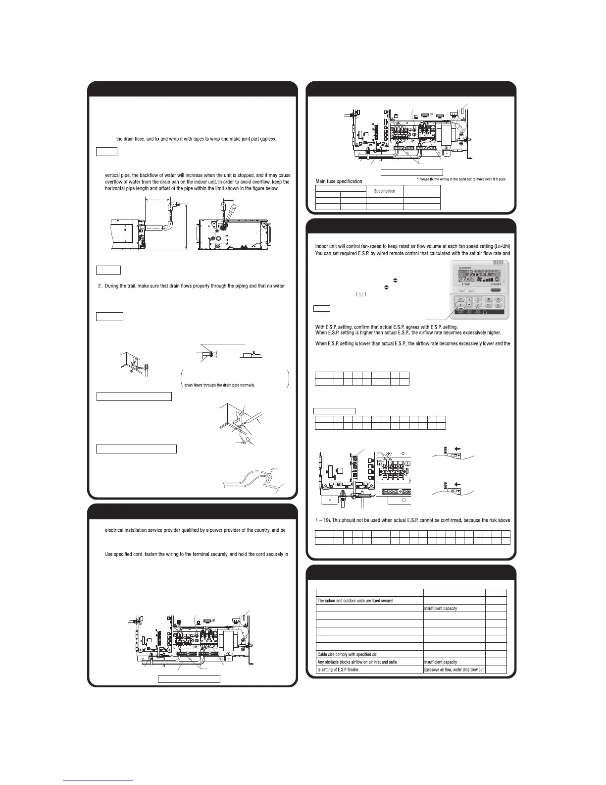
⑨Wiring-out position and wiring connection
●Electrical installation work must be performed according to the installation manual by an
executed according to the technical standards and other regulations applicable to electrical
installation in the country.
Be sure to use an exclusive circuit.
●
order not to apply unexpected stress on the terminal.
●Do not put both power source line and signal line on the same route. It may cause miscom-
munication and malfunction.
●For the details of electrical wiring work, see attached instruction manual for electrical wiring
work.
1. Remove a lid of the control box (2 screws).
2. Hold each wiring inside the unit and fasten them to terminal block securely.
3. Fix the wiring with clamps.
4. Install the removed parts back to original place.
Power source line
Signal line
Remote control line
Earth
*
Single unit wiring connection
Multi unit wiring connection
Earth
Main fuse
*
Indoor - Outdoor connecting line
Remote control line
⑩External static pressure setting
⑨Wiring-out position and wiring connection (continued)
You can set External Static Pressure (E.S.P.) by method of MANUAL SETTING on remote control.
pressure loss of the duct connected.
This will cause water leakage if water splashes.
cooling or heating may become ineffective.
In order to reduce the risk above the factory E.S.P. setting is set within the range of 80 – 150 Pa
(E.S.P. setting No. 8 – 15). Be sure to use within the range of 80 – 150 Pa in actual operations. If
actual E.S.P. is lower than 80 Pa, it may cause water leakage.
※
If 1 – 7 is selected for the setting No. on the remote control, the setting No. shows No. 8.
If 16 – 20 is selected for the setting No. on the remote control, the setting No. shows No. 15.
Factory default is No. 8.
If SW8-4 is turned to “ON”, E.S.P. setting range can be changed to 10 – 200 Pa (E.S.P. setting No.
becomes higher.
※
If 20 is selected for the setting No. on the remote control, the setting No. shows No. 19.
You can NOT set E.S.P. by wireless remote control.
● How to set E.S.P. by wired remote control
①Push "◆" marked button(E.S.P. button).
② Select indoor unit No. by using button.
③ Select setting No. by using button and
set E.S.P. by button.
See detailed procedure in technical manual.
SW8-4:ON (E.S.P. setting No. 1-19 )
SW8-4:OFF (E.S.P. setting No. 8-15 )
Setting No.
E.S.P. (Pa)
1
10
2
20
3
30
4
40
5
50
6
60
7
70
8
80
9
90
10
100
11
110
12
120
Setting No.
E.S.P (Pa)
8
80
9
90
10
100
11
110
12
120
13
130
14
140
15
150
13
130
14
140
15
150
16
160
17
170
18
180
19
200
※ If 13-20 is selected for the setting No. on the remote control, the setting No. shows No. 12.
※ Factory default is No. 8.
Setting No.
E.S.P. (Pa)
1
10
2
20
3
30
4
40
5
50
6
60
7
70
8
80
9
90
10
100
11
110
12
120
Notice
The Case of FDU-F
⑧Drain pipe (continued)
1. Conduct a drain test after completion of the electrical work.
leaks from connections.
3. In case of a new building, conduct the test before it is furnished with the ceiling.
4. Be sure to conduct this test even when the unit is installed in the heating season.
1.
Supply about 2000 cc of water to the unit through the air outlet by using a feed water pump.
2. Check the drain while cooling operation.
●If the bottom drain piping can be done with a
descending gradient (1/50-1/100), it is possible to
connect the pipes as shown in the drawing below.
●Uncouple the connector CNR for the drain motor as
illustrated in the drawing on the right.
Note: If the unit is run with the connector coupled,
drain water will be discharged from the upper
drain pipe joint, causing a water leak.
P.C. board
Insert water supply hose
for 20mm ~ 30mm to
supply water.
(Insert hose facing
toward bottom.)
Attached drain hose clamp
Drain
piping
Main
unit
Drain situation can be checked with transparent socket.
If the electrical work has not been completed, connect a convex
joint in the drain pipe connection to provide a water inlet.
Then, check if water leaks from the piping system and that
Pour water into a convex joint
Remove grommet
Make sure to Install
it back after test.
Connecting port of top drain pipe
Insulating material
Transparent soft tube
(Prepare on site)
Rubber stopper (to be removed)
Connecting port of bottom drain pipes
(Outside diameter:20mm)
Standard hard polyvinyl
chloride pipes
( )
Drain test
Procedures
Outline of bottom drain piping work
Uncoupling the drain motor connector
Main fuse
4. Insulate the drain pipe.
●Be sure to insulate the drain socket and rigid PVC pipe installed indoors otherwise it may
cause dew condensation and water leakage.
※
After drainage test implementation, cover the drain socket part with pipe cover (small size),
then use the pipe cover (big size) to cover the pipe cover (small size), clamps and part of
●The position for drain pipe outlet can be raised up to 600mm above the ceiling. Use elbows
for installation to avoid obstacles inside ceiling. If the horizontal drain pipe is too long before
Otherwise, the construction point makes it same as drain pipe construction.
Drain up
600 max
295-325
100 or less
 Loading...