-
37
-
Technical data
‘19 • HM-T-340
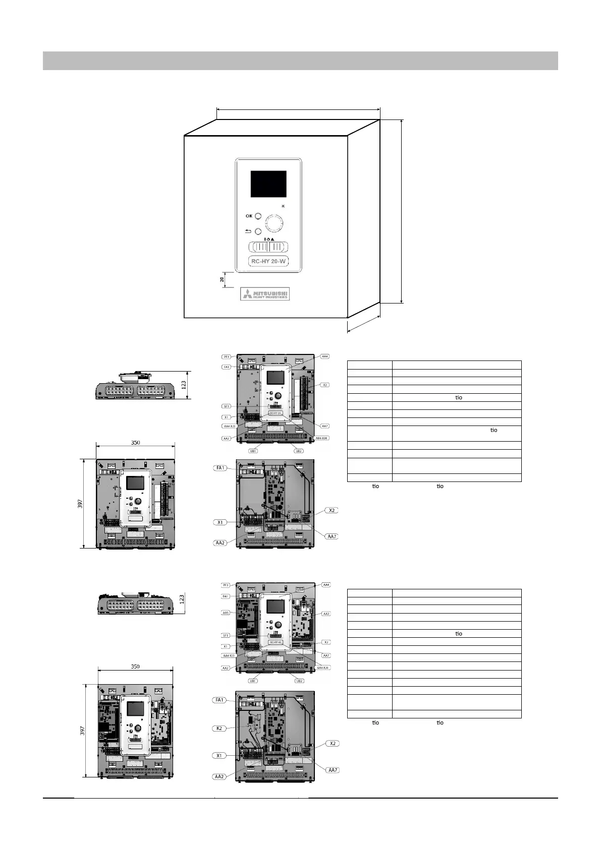
Dimensions
AA2 Base card
AA4 Display unit
AA4-XJ3 USB socket
AA4-XJ4 Service outlet (No func n)
AA7 Extra relay circuit board
FA1 Miniature circuit breaker
X1 Terminal block, incoming electrical supply
X2 Terminal block, control signal circula n
pump, sensors, AUX inputs and heat pump
SF1 Switch
PF3 Serial number plate
UB1 Cable grommet, incoming supply electricity,
power for accessories
UB2 Cable gland, signal
Designa ns in components loca ns according to
standard IEC 81346-1 and 81346-2
AA2 Base card
AA3 Input circuit board
AA4 Display unit
AA4-XJ3 USB socket
AA4-XJ4 Service outlet (No func n)
AA5 Accessory board
AA7 Extra relay circuit board
FA1 Miniature circuit breaker
X1 Terminal block, incoming electrical supply
X2 Terminal block, AUX4 – AUX6
SF1 Switch
PF3 Serial number plate
UB1 Cable grommet, incoming supply electricity,
power for accessories
UB2 Cable gland, signal
Designa ns in components loca ns according to
standard IEC 81346-1 and 81346-2
354
123
400
Symbol Content
Symbol Content
Outside
:
RC-HY20/40
(3) Controller
Meaning of symbol
Meaning of symbol
Controller
Outside : RC-HY20/40-W
Inside : RC-HY20-W
Inside : RC-HY40-W
#
 Loading...