'19 • SCM-SM-276
-
161
-
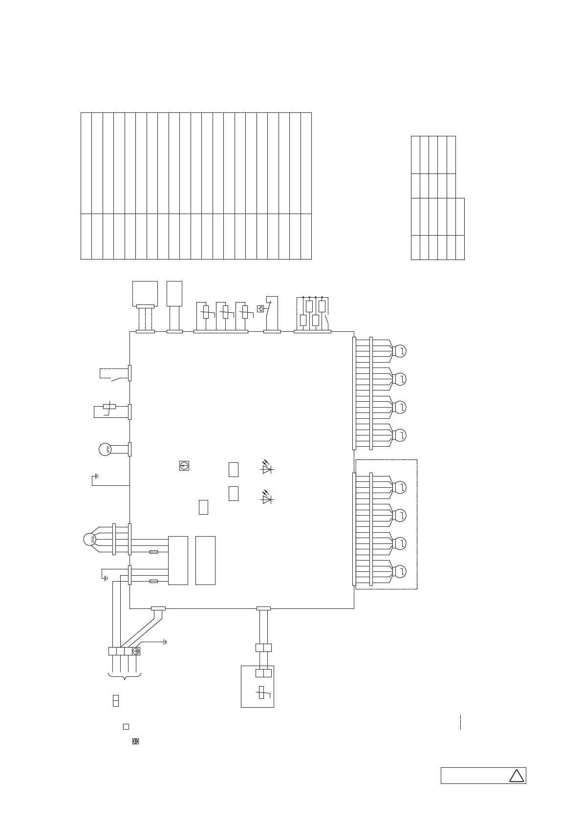
Operation check,drain pump motor test run
Temperature sensor(Remote control)
Model capacity setting
SW6
Terminal block(Power source)( □ mark)
TB1
TB2
SW2
Remote control communication address
SW7-1
Thi-A
Thi-R1,2,3
Th
C
Terminal block(Signal line)( □ mark)
Temperature sensor(Return air)
Temperature sensor(Heat exchanger)
Drain pump motor
Fan motor
DM
Fuse
F1,2
Connector
CNB - Z
FMi
Description
Item
Meaning of marks
Draft prevention function motor
AM1 - 4
Louver motor
Float switch
LM1-4
FS
Indication lamp(Red-Inspection)
LED・2
Indication lamp(Green-Nomal operation)
LED・3
PIS
Motion sensor
Humidity sensor
HS
SW5
Plural units Master/Slave setting
Color marks
Mark Color
Blue
BK
BL
Brown
Orange
BR
OR
Red
RD
Black
Mark Color
Yellow
WH
YE
Gray
Yellow/Green
GY
YE/GN
White
CNTA
BL
12
Th -A
CNI
BL
CNJ1
WH
CNJ2
GY
AM4AM1 AM2 AM3
6
5
4
3
2
1
CNN
YE
Thi-R3
Thi-R2
Thi-R1
t°
t°
t°
2
1
CNC
WH
CNH
BK
12
t°
i
DM
12
CNR
WH
M
CNM1
WH
FM
i
M
F2
CNB
BK
1 2 3 4 5 6 7 8 9 10 11 12 13 14 15 16 17 18 19 20
2
1
RD
RD
RD
RD
YE
BK
BK
YE
1 4 5 6 7
FS
X
Y
X
Y
t°
Remote control
TB2
WH
BK
Th
C
TB1
YE/GN
1 2 3 4 5 6 7 8 9 10 11 12 13 14 15 16 17 18 19 20
BLRD BR OR WH
+12
+12
(2.0A)
YE/GN
※1
BKBK
RDWH
LM4LM1 LM2 LM3
MM
1
M M
2 3 4 5 1 2 3 4 5 1 2 3 4 5 1 2 3 4 5
MM
1
M M
BK
2 3 4 5 1 2 3 4 5 1 2 3 4 5 1 2 3 4 5
BK BK BK BK BK BK BK BK BK
WH WH WH WH WH WH WH WH WH WHBL BL BL BL BLBL BL BL BL
BL
RD RD RD RD RD RD RD RD RD RD
E1
F1
CNWO
WH
135
YE/GN
RD
(3.15A)
WH
Power circuit
Indoor unit PCB
CNL
BK
3
1
2
BK
BK
BK
Option
1
2
(volt-free contact)
HS
BK
BK
Remote operation input
BK BK BK BK BK BK BK BK BK BK RD RD RD RD RD RD RD RD RD RD
CNJ3
WH
CNJ4
WH
WH WH WH WH WH WH WH WH WH WHBL BL BL BL BL
BL
BL
BL BL
BL
1
2
Earth
3
Power source line
Signal line
1 2
3
CNW3
WH
1
3
WH
BL
The line between
indoor unit and outdoor unit
[ ]
XR1
XR5
(Operation)
(Heating)
(Compressor ON)
(Inspection)
Prepare on site
XR2
XR3
XR4
1
2
3
4
5
6
+12
Remote operation input
(volt-free contact)
CNT
BL
CNM2
WH
BLRD BR OR WH
PIS
3
1
2
SW2
SW6SW7
LED・3LED・2
SW5
Prepare on site
Notes 1. indicates wiring on site.
2. See the wiring diagram of outdoor unit about the line between
3. Use twin core cord(0.3mm )at remote control line.
See spec sheet of remote control in case that the total length is more than 100m.
2
indoor unit and outdoor unit.
4. Do not put remote control line alongside power source line.
5. Draft prevention function(※1) is provided on the panel TC-PSAE-5AW-E only.
(c)
4-way ceiling cassette type (FDTC)
Models FDTC25VH, 35VH, 50VH, 60VH
PJF000Z516
A
 Loading...