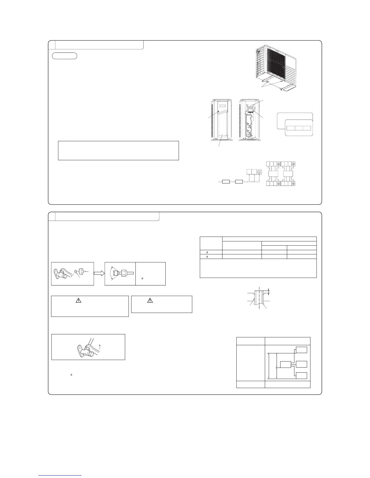
INSTALLATION OF OUTDOOR UNIT
2
Drainage
There are 2 holes in the bottom panel of the outdoor unit to drain condensation.
View of Terminal block
Install the outdoor unit so it will be horizontal.
Also, secure the legs of the unit to a firm foundation to prevent any instabilities.
Secure it firmly so the unit will not fall during earthquakes and from sudden gusts of wind.
In areas where the temperatures drop below 0˚C for several continuous days, do
not install a drain elbow. (water discharge could stop due to freezing.)
Connection of the power supply cable and the connecting cables
for indoor and outdoor units.
This multi-type room air conditioner receives its power from outside.
To ensure correct connections, mark each ends of the cables with number, A and B.
It is important to use the same number the corresponding cables and pipes.
An earth leakage breaker and a circuit breaker must be installed.
Their capacities are 25A.
①
Remove the service panel. (Remove the screw of the service panel.)
Remove the terminal cover. (Remove the screw of the terminal cover.)
②
③
⑤
④
Connect the power supply cable and the connection wire securely to the terminal block.
〔POWER SUPPLY CODE 〕
CENELEC code for cables requiring fields cables. H05RNR3G4.0
〔INTERCONNECTING WIRING CODE〕
CENELEC code for cables requiring fields cables. H05RNR4G1.5
1) In wiring, make sure that the wire terminal numbers of outdoor unit terminal
block are match to the wire terminal numbers of indoor unit terminal block.
2) Terminal number A of the outdoor unit is used for A indoor unit and terminal
number B for B indoor unit respectively.
After connecting the wire, use wiring clamps to secure the wiring.
Fit the terminal cover and the service panel.
outdoor unit
unit A
unit A
indoor unit
L N
Circuit
breaker
Earth
leakage
breaker
CONNECTION OF REFRIGERANT PIPINGS
3
●
●
●
●
●
●
●
●
●
●
●
Copper pipe
diameter
Clutch typr flare tool for
R410A
Conventional (R22) flare tool
Clutch type Wing nut type
Measurement B
(
mm
)
6.35 0.0〜0.5 1.0〜1.5 1.5〜2.0
9.52 0.0〜0.5 1.0〜1.5 1.5〜2.0
[Connection of pipes]
NOTE
Cover the pipes with tape so that dust and sand do not enter the pipe until they are
When connecting the pipes to the outdoor unit, be careful about the discharge of fluorocarbon
Make sure to match the pipes between the indoor unit and the outdoor unit with the
connected.
gas or oil.
correct operation valves.
Outdoor
Press
Remove
A
90±0.5°
Dimension A
Liquid side 9.1dia.
Gas side
9.52 : 13.2dia
○
Remove the flared nuts.
(on both liquid and gas sides)
○Install the removed flared nuts to the pipes
to be connected, then flare the pipes.
Do not apply excess torque to the flared nuts.
Otherwise, the flared nuts may crack depending
on the conditions and refrigerant leak may occur.
CAUTION
Do not apply refrigerating machine
oil to the flared surface.
CAUTION
Measurement B
Flaring
block
Copper pipe
Outdoor
Connection
Liquid side
Gas side
Ensure that there are no gas leaks from the pipe
joints by using a leak detector or soap water.
Gas Leakage Test
●
○Connect the pipes on both liquid and gas sides.
○Tighten the nuts to the following torque.
Liquid side : 14.0
〜18.0N・m
(
1.4〜1.8kgf・m
)
Gas side (
9.52): 33.0〜42.0N・m (3.3〜4.2kgf・m)
piping length
hight difference
length of chargeless
refrigerant pipe
one indoor unit MAX 25m
all indoor unit MAX 30m
30m
MAX
25m
MAX 15m
MAX 15m
outdoor
unit
indoor
unit
indoor
unit
indoor
unit
[Limit]
unit A unit B
POWER
SUPPLY
Use a flare tool designed for R410A or a conventional flare tool. Please note that
measurement B (protrusion from the flaring block) will vary depending on the type of a
flare tool in use.
If a conventional flare tool is used, please use copper pipe gauge or a similar
instrument to check protrusion so that you can keep measurement B to a correct value.
Drain hole
Terminal cover
Service panel
Screw Screw
1 2 3
1 2 3
unit B
unit B
1 2 3
1 2 3
 Loading...