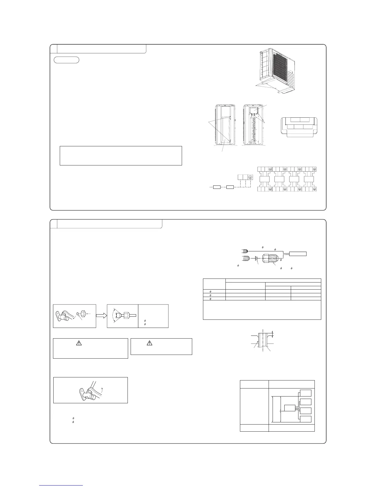
INSTALLATION OF OUTDOOR UNIT
2
Drainage
There are 3 holes in the bottom panel of the outdoor unit to drain condensation.
View of Terminal block
Install the outdoor unit so it will be horizontal.
Also, secure the legs of the unit to a firm foundation to prevent any instabilities.
Secure it firmly so the unit will not fall during earthquakes and from sudden gusts of wind.
In areas where the temperatures drop below 0˚C for several continuous days, do
not install a drain elbow. (water discharge could stop due to freezing.)
Connection of the power supply cable and the connecting cables
for indoor and outdoor units.
This multi-type room air conditioner receives its power from outside.
To ensure correct connections, mark each ends of the cables with number, A to D. It
is important to use the same number the corresponding cables and pipes.
An earth leakage breaker and a circuit breaker must be installed.
Their capacities are 25A.
①
Remove the service panel.(Remove the 2 sets screws of the service panel.)
Remove the terminal cover.(Remove the 2 sets screws of the terminal cover.)
②
③
⑤
④
Connect the power supply cable and the connection wire securely to the terminal block.
〔POWER SUPPLY CODE〕
CENELEC code for cables requiring fields cables. H05RNR3G4.0
〔INTERCONNECTING WIRING CODE〕
CENELEC code for cables requiring fields cables. H05RNR4G1.5
1) In wiring, make sure that the wire terminal numbers of outdoor unit terminal
block are match to the wire terminal numbers of indoor unit terminal block.
2) Terminal number A of the outdoor unit is used for A indoor unit and terminal
number B for B indoor unit respectively.
After connecting the wire, use wiring clamps to secure the wiring.
Fit the terminal cover and the service panel.
outdoor unit
1 2 31 2 3 1 2 3 1 2 3
1 2 3
1 2 3
1 2 3
unit A
unit B
unit C
unit A unit B
indoor unit
unit C
1 2 3
unit D
unit D
L N
Circuit
breaker
Earth
leakage
breaker
CONNECTION OF REFRIGERANT PIPINGS
3
Regarding the change in the sizes of gas side pipes (usage of the variable joints);
If a 5.0, 6.0 kw class indoor unit (gas side pipe 12.7) is going to be connected to the
operation valves (9.52), variable joints available as accessories must be applied to the
gas side operation valves.
[Examples of use of variable diameter joints]
Connection of indoor unit of Class 5.0 to A unit.
●
●
●
●
●
●
●
●
●
●
●
●
●
●
Operation
valveforroomA
Liquidsideoperationvalve(
6.35)
6.35pipe
5.0kw
Indoorunit
Gassideoperation
valve(
9.52)
Copperpacking
①Variablediameterjoint
(
9.52- 12.7)
12.7pipe
Use a flare tool designed for R410A ora conventional flare tool. Please note that
measurementB(protrusionfromtheflaringblock)willvarydependingonthetypeofa
flaretoolinuse.
If a conventional flare tool is used, please use a copper pipe gauge or a similar
instrumenttocheckprotrusionsothatyoucankeepmeasurementBtoacorrectvalue.
Copperpipe
diameter
Clutchtypeflaretoolfor
R410A
Conventional
(
R22
)
flaretool
Clutchtype Wingnuttype
MeasurementB
(
mm
)
6.35 0.0〜0.5 1.0〜1.5 1.5〜2.0
9.52 0.0〜0.5 1.0〜1.5 1.5〜2.0
12.7 0.0〜0.5 1.0〜1.5 2.0〜2.5
Securely fit the copper packing between the operation valve and the variable
diameter joint to prevent shifting.
[Connection of pipes]
NOTE
Cover the pipes with tape so that dust and sand do not enter the pipe until they are
When connecting the pipes to the outdoor unit, be careful about the discharge of fluorocarbon
Make sure to match the pipes between the indoor unit and the outdoor unit with the
connected.
gas or oil.
correct operation valves.
Outdoor
Press
Remove
A
90±0.5°
Dimension A
Liquid side 9.1dia.
Gas side
9.52 : 13.2dia
12.7 : 16.2dia.
○
Remove the flared nuts.
(on both liquid and gas sides)
○Install the removed flared nuts to the pipes
to be connected, then flare the pipes.
Do not apply excess torque to the flared nuts.
Otherwise, the flared nuts may crack depending
on the conditions and refrigerant leak may occur.
CAUTION
Donotapplyrefrigeratingmachine
oiltotheflaredsurface.
CAUTION
Measurement B
Flaring
block
Copper pipe
Outdoor
Connection
Liquid side
Gas side
When the total refrigerant pipe lenght for all the
rooms exceeds the lenght of the uncharged pipe
(40m), additional refrigerant is required.
(If 40m or less, additional charge is not required.)
Additional charge amount per meter = 20g/m
●
Ensure that there are no gas leaks from the pipe
joints by using a leak detector or soap water.
Gas Leakage Test
●
○Connect the pipes on both liquid and gas sides.
○Tighten the nuts to the following torque.
Liquid side : 14.0
〜18.0N・m
(
1.4〜1.8kgf・m
)
Gas side (
9.52): 33.0〜42.0N・m (3.3〜4.2kgf・m)
(
12.7): 49.0〜61.0N・m (4.9〜6.1kgf・m)
piping length
hight difference
length of chargeless
refrigerant pipe
one indoor unit MAX 25m
all indoor unit MAX 70m
40m
MAX
25m
MAX 20m
MAX 20m
outdoor
unit
indoor
unit
indoor
unit
indoor
unit
indoor
unit
[Limit]
4
AIR PURGING
NOTE : Fully open the operation valves (on both liquid and gas sides) after completing air purging.
● Since the system uses service ports differing in diameter from those found
on the conventional models, a charge hose (for R22) presently in use is not
applicable. Please use one designed specifically for R410.A.
●Please use an anti-reverse flow type vacuum pump adapter so as to prevent
vacuum pump oil from running back into the system. Oil running back into
an air-conditioning system may cause the refrigerant cycle to break down.
● Remove the cap on both gas and liquid sides before starting operation.
● After completing the operation, do not forget to tighten the cap (gas may leak).
●Conduct air purging for all connected indoor units.
Procedure
(1) Secure all flare nuts on both indoor and outdoor sides to
prevent leaks from the pipes.
(2) Connect the operation valves, charge hose, manifold
valve and vacuum pump as shown in the right figure.
(3) Fully open the handle Lo for the manifold valve, and
pump a vacuum for 15 minutes. Ensure that the meter
is indicating -0.1MPa (-76cmHg).
(4) After vacuuming, fully open the operation valve (both
liquid and gas sides) with a hexagon wrench.
(5) Remove the charge hose from service port.
(6) Repeat the above steps (1) ~ (5) for all connected indoor units.
(7) Ensure that there are no gas leaks from the joints in the indoor and outdoor units.
Open
Open
5
HEAT INSULATION FOR JOINTS
Heat insulation for joints
Vinyl
tape
Position so
the slit
comes on top.
Cover the joint with
insulation material
for the indoor unit
and tape it.
Pipe clamp
Pipes
Crossover wires
Exterior tape
Drain hose
Tapping screw
Apply exterior tape and
shape along the place
where the pipes will be
routed. Secure to the wall
with a pipe clamp. Be
careful not to damage the
pipes and the wires.
7
BEWARE OF WRONG CONNECTIONS IN
REFRIGERANT PIPING AND WIRING.
●Make sure to match the piping and wiring from each unit to the
●Be careful because if connections are wrong, normal operation
cannot be achieved and may damage the compressor.
outdoor unit.
[Correct connections]
[Example of wrong connections]
Piping
Wiring
Indoor unit
Indoor unit
D unit
C unit
B unit
A unit
Outdoor
unit
D unit
C unit
B unit
A unit
Outdoor
unit
D
C
A
B
D
C
A
B
EARTHING WORK
○Earth work shall be carried out without fail in order to prevent electric
shock and noise generation.
○The connection of the earth cable to the following substances causes
dangerous failures, therefore it shall never be done. (City water pipe,
Town gas pipe, TV antenna, lightning conductor, telephoneline, etc.)
Check the following points again after completion of the installation, and before
turning on the power.
Conduct a test run again and ensure that the unit operates properly.
At the same time, explain to the customer how to use the unit and how to take
care of the unit following the installation manual.
If the compressor does not operate after the operation has started, wait for 5-10
minutes. (This may be due to delayed start.)
(Three-minute restart preventive timer)
When the air conditioner is restarted or when changing the operation, the unit will
not start operating for approximately 3minutes. This is to protect the unit and it is
not a malfunction.
After installation
Test run
□
The power supply voltage is correct as the rating.
□No gas leaks from the joints of the operation valve.
□Power cables and crossover wires are securely fixed to the terminal board.
□Each indoor and outdoor unit is properly connected (no wrong wiring or piping).
□Operation valve is fully open.
□Refrigerant has been additionally charged (when the total pipe length exceeds
the refrigerant charged pipe length).
□The pipe joints for indoor and outdoor pipes have been insulated.
□Earthing work has been conducted properly.
□Air conditioning and heating are normal.
□No abnormal noise.
□Water drains smoothly.
□Protective functions are not working.
□Operation of the unit has been explained to the customer.
□The remote control is normal.
Operation of indicator lamps
INDICATION LAMP
LED E (1)
1 TIME FLASH
2 TIME FLASH
3 TIME FLASH
4 TIME FLASH
5 TIME FLASH
6 TIME FLASH
7 TIME FLASH
8 TIME FLASH
LIGHT ON
FOUR SEC LIGHT
AND
FOUR SEC OFF
COLOR
RED
SELF DIAGNOSIS FUNCTION BY LED E
FUNCTION
WARNING LAMP
CURRENT CUT
TROUBLE OF OUTDOOR UNIT
OVER CURRENT
TRANSMISSION ERROR IN OUTDOOR UNIT PCB
OVER HEAT OF COMPRESSOR
ERROR OF SIGNAL TRANSMISSION
LOCK OF COMPRESSOR
SENSOR ERROR (EXCEPT DISCHARGE PIPE SENSOR)
OUTDOOR FAN MOTOR ERROR
DISCHARGE PIPE SENSOR ERROR
Installation test check points
6
TEST RUN AND HANDLING INSTRUCTIONS
drain hole
Terminal cover
Service panel
Screw
Operation valve
for room D
Operation valve
for room C
Operation valve
for room B
Operation valve
for room A
tightening torque (N·m)
Operation valve cap
tightening torque (N·m)
Check joint blind nut
6.35 (1/4")
9.52 (3/8")
12.7 (1/2")
20
30
25
35
10
12
Operation valve size
(mm)
Securely tighten the operation valve cap and the check joint blind nut after adjustment.
(three-way valve)
Charge hose
(Designed specifically for R410A)
Compound pressure gauge
Pressure gauge
Gauge Manifold
(Designed specifically for R410A)
Handle Hi.
Vacuum pump
Vacuum pump adapter
(Anti-reverse flow type)
(Designed specifically for R410A)
Charge hose
(Designed specifically for R410A)
Check joint
-0.1MPa
(-76cmHg)
Handle Lo
Operation Valve
Operation Valve
(two-way valve)
Operation Valve
Cap
Operation Valve
Cap
Screw
unit A unit B
unit C
unit D
POWER
SUPPLY
A
RPC012A913
 Loading...